Illuminating apparatus

a technology of illumination apparatus and illumination beam, which is applied in the direction of point-like light source, light and heating apparatus, transportation and packaging, etc., can solve the problems of wasting energy in irradiating areas, the inability to change the light reflecting angle,

Inactive Publication Date: 2010-03-16
HON HAI PRECISION IND CO LTD
View PDF3 Cites 13 Cited by
  • Summary
  • Abstract
  • Description
  • Claims
  • Application Information

AI Technical Summary

Benefits of technology

[0005]To improve a light utilizing efficiency, fluorescent lamps usually have a lampshade for reflecting light back to a side that is need to be irradiated. Although a number of lampshades having different shapes are developed to improve a light reflecting efficiency; however, once the lampshades are made, they can't be modified to change light reflecting angles. In some practical illuminating applications, an area need to be irradiated may change together with time or other conditions. It is a waste of energy to irradiate areas that are not need for illumination.

Problems solved by technology

Although a number of lampshades having different shapes are developed to improve a light reflecting efficiency; however, once the lampshades are made, they can't be modified to change light reflecting angles.
It is a waste of energy to irradiate areas that are not need for illumination.

Method used


Image

  • Illuminating apparatus
  • Illuminating apparatus
  • Illuminating apparatus

Examples


Embodiment Construction

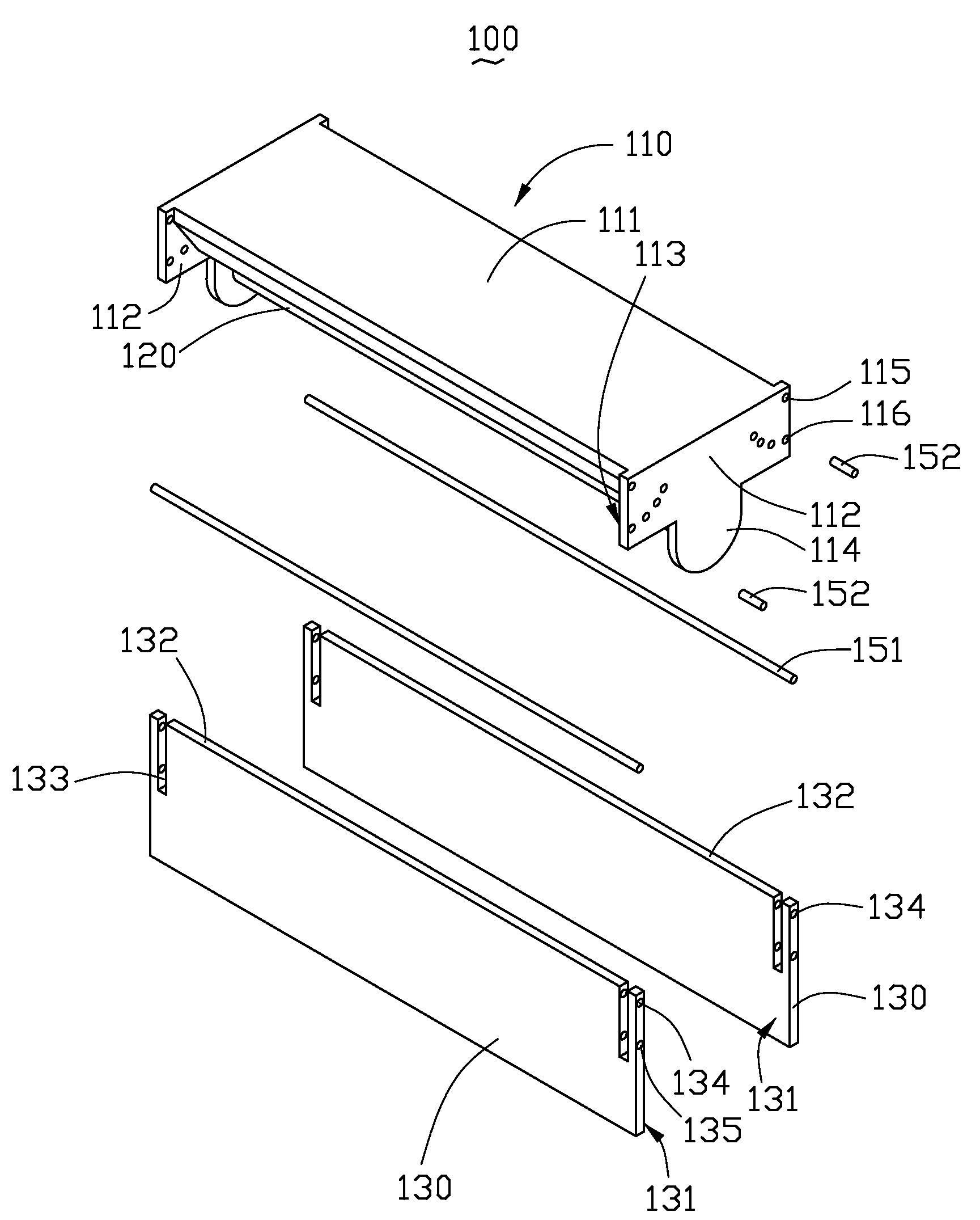
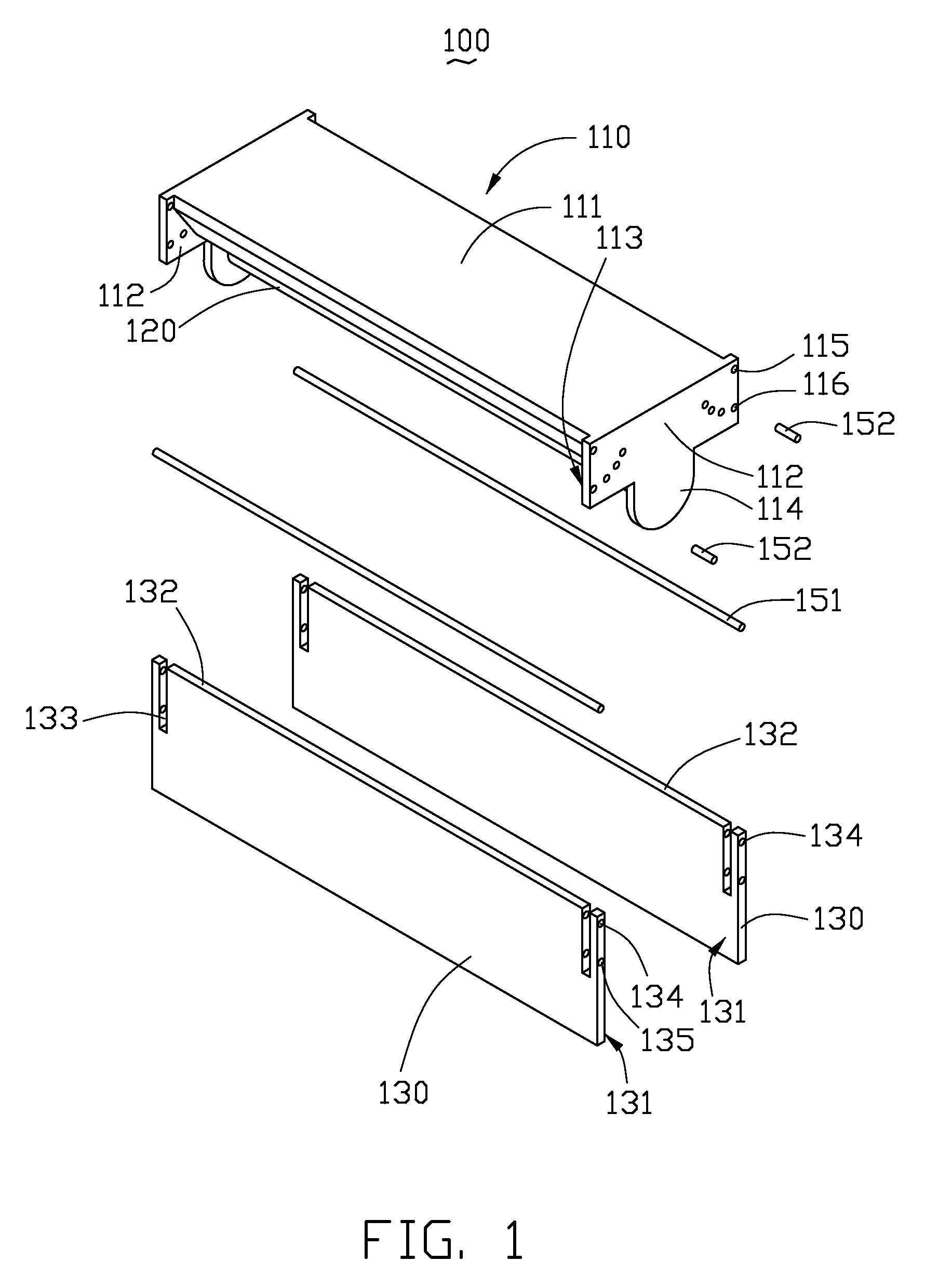
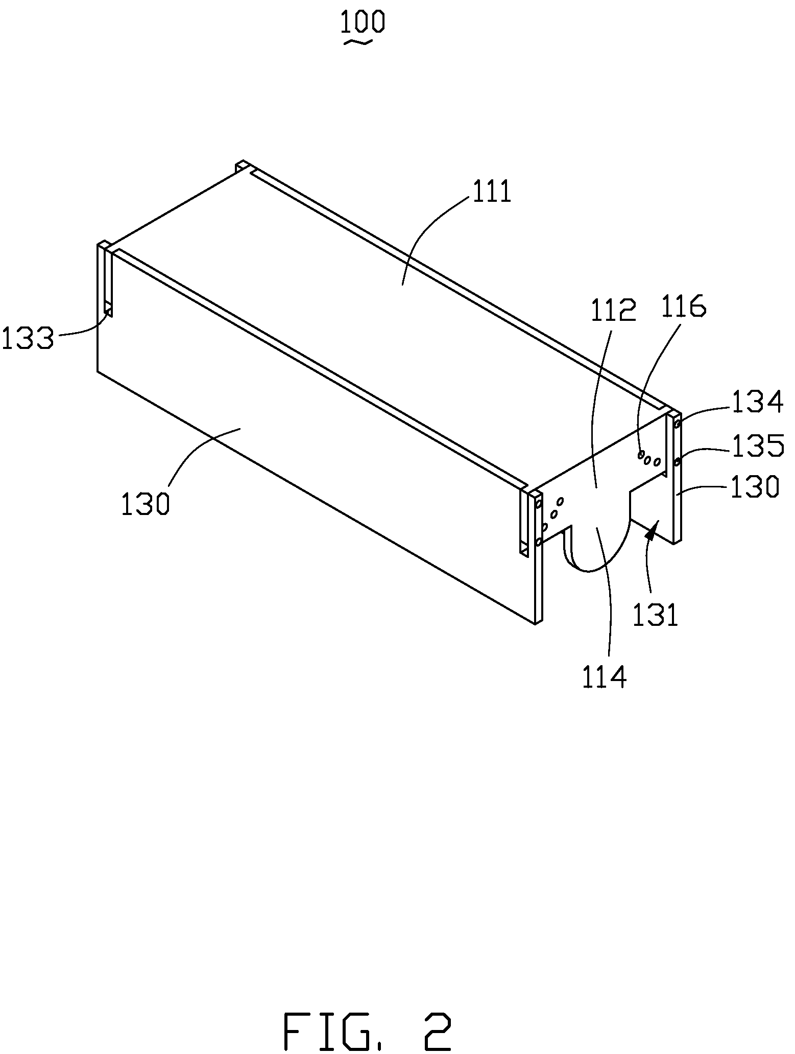
[0013]Reference will now be made to the drawings to describe described an exemplary embodiment of the illuminating apparatus in detail.

[0014]Referring to FIG. 1 and FIG. 2, an illuminating apparatus 100 includes a light source holder 110, a linear light source 120 and two elongated reflecting plates 130.

[0015]The light source holder 110 is configured for holding the linear light source 120 and the elongated reflecting plates 130, and includes a base 111 and two opposite end plates 112 extending from two opposite ends of the base 111. In this description, unless the context indicates otherwise, the configuration of only one of the end plates 112 is described.

[0016]In this embodiment, each of the end plates 112 has an inner sidewall 113. Two pivot holes 115 are defined in two ends of each of the end plates 112, respectively. Each of the pivot holes 115 is adjacent to a corresponding long side of the base 111. A number of through holes 116 are defined in the end plates 112. Each of the...


PUM


Abstract

An exemplary illuminating apparatus comprises a light source holder, a linear light source and two elongated reflecting plates. The linear light source is mounted on the light source holder. The elongated reflecting plates are mounted on opposite sides of the light source holder. Each of the elongated reflecting plates is rotatable about a rotation axis relative to the light source holder.

Description

BACKGROUND[0001]1. Technical Field[0002]The present disclosure relates to an illuminating apparatus, and particularly, to an illuminating apparatus having an adjustable illumination range.[0003]2. Description of Related Art[0004]Currently, fluorescent lamps are widely used as a light source to obtain natural light in a wide variety of illuminating apparatuses, for example, indoor, outdoor and corridor illuminations.[0005]To improve a light utilizing efficiency, fluorescent lamps usually have a lampshade for reflecting light back to a side that is need to be irradiated. Although a number of lampshades having different shapes are developed to improve a light reflecting efficiency; however, once the lampshades are made, they can't be modified to change light reflecting angles. In some practical illuminating applications, an area need to be irradiated may change together with time or other conditions. It is a waste of energy to irradiate areas that are not need for illumination.[0006]Fo...

Claims


Application Information

Patent Timeline
Patent Type & Authority Patents(United States)
IPC IPC(8): B60Q1/14
CPCF21V7/10F21V14/04F21V17/02F21Y2103/00
Inventor LIN, TSUNG-YU
Owner HON HAI PRECISION IND CO LTD
Why Eureka
Try Eureka