Light guide plate and method for manufacturing the same

a technology of light guide plate and light guide plate, which is applied in the direction of lighting device details, lighting and heating apparatus, instruments, etc., can solve the problems of difficult to accurately configure the optical characteristics of the light guide plate b, affecting the uniformity of light output, etc., to achieve optimal optical characteristics, convenient control, and easy control of the arrangement and distribution of light diffusing structur

Inactive Publication Date: 2006-06-08
INNOLUX CORP
View PDF12 Cites 30 Cited by
  • Summary
  • Abstract
  • Description
  • Claims
  • Application Information

AI Technical Summary

Benefits of technology

[0011] The light diffusing structures are formed within the light guide plate, which protects the light diffusing structures from being damaged. In addition, the laser engraving method and the ultrasonic engraving method can be conveniently controlled, so that the arrangement and distribution of the light diffusing structures can be easily controlled. This enables the light guide plate to be configured with optimal optical characteristics, thereby yielding an improved light utilization ratio.

Problems solved by technology

Liquid crystal display (LCD) devices are commonly used as display devices for compact electronic apparatuses, because they not only provide good quality images with little power but also are very thin.
However, the light diffusing structures 120 are liable to be damaged during transportation or handling of the light guide plate 10.
In other words, it is difficult to accurately configure the optical characteristics of the light guide plate 10′.
In particular, it is difficult to control the uniformity of light that will be output from the light emitting surface 160′ of the light guide plate 10′ in use.

Method used


Image

  • Light guide plate and method for manufacturing the same
  • Light guide plate and method for manufacturing the same
  • Light guide plate and method for manufacturing the same

Examples


first embodiment

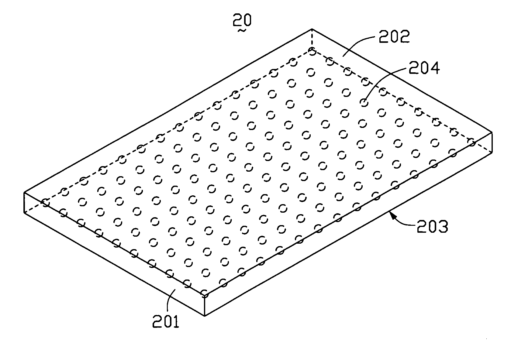
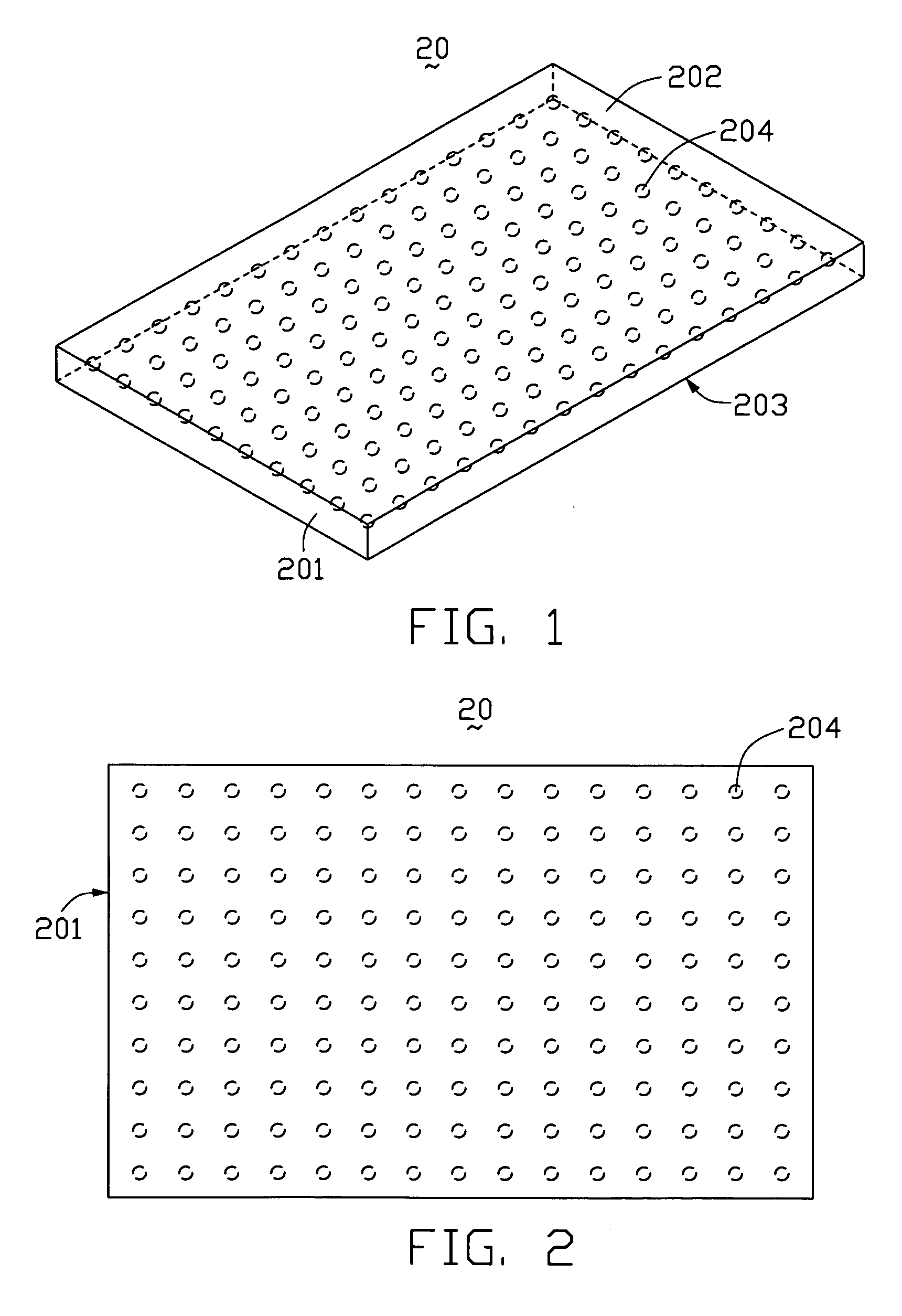
[0032] Referring to FIG. 1 and FIG. 2, a flat light guide plate 20 according to the present invention includes a light incident surface 201,, a light emitting surface 202 adjoining the light incident surface 201, and a bottom surface 203 opposite to the light emitting surface 202. The light guide plate 20 further includes a plurality of light diffusing structures 204 formed therein. The light diffusing structures 204 can be formed by a laser engraving method or an ultrasonic engraving method (see below). In the illustrated embodiment, the spherical light diffusing structures 204 are spherical, and are arranged in a single plane in a regular m×n type of matrix within the light guide plate 20.

[0033] Light beams from a light source (not shown) adjacent to the light incident surface 201 enter the light guide plate 20 through the light incident surface 201, are scattered when reaching the light diffusing structures 204, and finally are emitted through the light emitting surface 202 unifo...

seventh embodiment

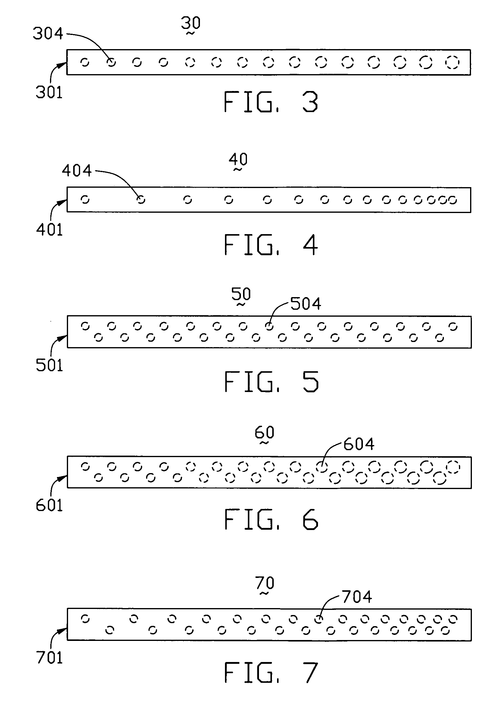
[0039] Referring to FIG. 8 and FIG. 9, a light guide plate 80 according the present invention includes a light incident surface 801, a light emitting surface 802 adjoining the light incident surface 801, a bottom surface 803 opposite to the light emitting surface 802, and a plurality of light diffusing structures 804. The light diffusing structures 804 are uniformly arranged in a single plane within the light guide plate 80, in a generally rectangular matrix. The light diffusing structures 804 in each column of light diffusing structures 804 are medially staggered in relation to the light diffusing structures 804 in each adjacent column of light diffusing structures 804. Similarly, the light diffusing structures 804 in each row of light diffusing structures 804 are medially staggered in relation to the light diffusing structures 804 in each adjacent row of light diffusing structures 804.

[0040]FIG. 10 is a schematic top view of a light guide plate according to an eighth embodiment of...

tenth embodiment

[0042] Referring to FIG. 12 and FIG. 13, a light guide plate 110 according the present invention includes a plurality of light diffusing structures 1104 formed therein. The light diffusing structures 1104 are formed as a continuous series of generally V-shaped light diffusing patterns 114. Each V-shaped light diffusing pattern may comprise two generally planar arrays of light diffusing structures 1104. Alternatively, each V-shaped light diffusing pattern may comprise two generally linear arrays of light diffusing structures 1104.

[0043] Referring to FIG. 14 and FIG. 15, a light guide plate 120 according to an eleventh embodiment of the present invention includes a plurality of light diffusing structures 1204 therein. The light guide plate 120 is similar to the light guide plate 110 of the tenth embodiment. However, the light guide plate 120 includes a plurality of light diffusing structures 1204 formed therein. The light diffusing structures 1204 are arranged as a plurality of separa...


PUM


Abstract

A light guide plate (20) includes a main body, a light incident surface (201), a light emitting surface (202), and a plurality of light diffusing structures (204), arranged within the main body according to a predetermined pattern. The light diffusing structures are formed using an engraving method. The light diffusing structures are formed within the light guide plate, which protects the light diffusing structures from being damaged. In addition, the laser engraving method and the ultrasonic engraving method can be conveniently controlled, so that the arrangement and distribution of the light diffusing structures can be easily controlled. This enables the light guide plate to be configured with optimal optical characteristics, thereby yielding an improved light utilization ratio.

Description

BACKGROUND [0001] 1. Field of the Invention [0002] The present invention relates to a light guide plate and a method for manufacturing the light guide plate. [0003] 2. General Background [0004] Liquid crystal display (LCD) devices are commonly used as display devices for compact electronic apparatuses, because they not only provide good quality images with little power but also are very thin. The liquid crystal molecules in a liquid crystal display do not emit any light themselves. The liquid crystal molecules have to be lit by a light source so as to clearly and sharply display text and images. Thus, a backlight module for an LCD is generally needed. A light guide plate is generally needed in a backlight module. [0005] A typical light guide plate is shown in FIG. 17. The light guide plate 10 includes a light incident surface 110, a light emitting surface 160 adjoining the light incident surface 110, a bottom surface 140 opposite to the light emitting surface 160, and a plurality of...

Claims


Application Information

Patent Timeline
Patent Type & Authority Applications(United States)
IPC IPC(8): F21V7/04
CPCG02B6/0036G02B6/0061G02B6/0065
Inventor LIN, CHING-HUANGLIN, WEN-BINCHANG, CHIH-HUNG
Owner INNOLUX CORP
Why Eureka
Try Eureka