High-collimation face type light source module and light output method thereof

A collimating surface type, light source module technology, applied in optics, light guides, optical components, etc., can solve the problems of prolonging battery life, unfavorable mass production, manufacturing difficulties, etc., to achieve the effect of improving light utilization rate

Active Publication Date: 2010-03-31
IND TECH RES INST
View PDF0 Cites 31 Cited by
  • Summary
  • Abstract
  • Description
  • Claims
  • Application Information

AI Technical Summary

Problems solved by technology

However, the light utilization rate of traditional liquid crystal displays is only 6% to 10%. For notebook computers, the power consumption of liquid crystal displays is about 30 to 40%. If the light utilization rate can be improved, the battery life can be greatly extended
[0003] In addition, the traditional method of using microlenses to improve the light utilization of transflective backlight sources, or using grating diffraction color splitting technology to replace traditional dye-absorbing color filters to improve light utilization, or using The three-dimensional disp

Method used


Image

  • High-collimation face type light source module and light output method thereof
  • High-collimation face type light source module and light output method thereof
  • High-collimation face type light source module and light output method thereof

Examples


Embodiment Construction

[0054] The technical means and effects used by the present invention to achieve the purpose will be described below with reference to the accompanying drawings, and the embodiments listed in the following drawings are only auxiliary descriptions, but the present invention is not limited to the drawings and the embodiments.

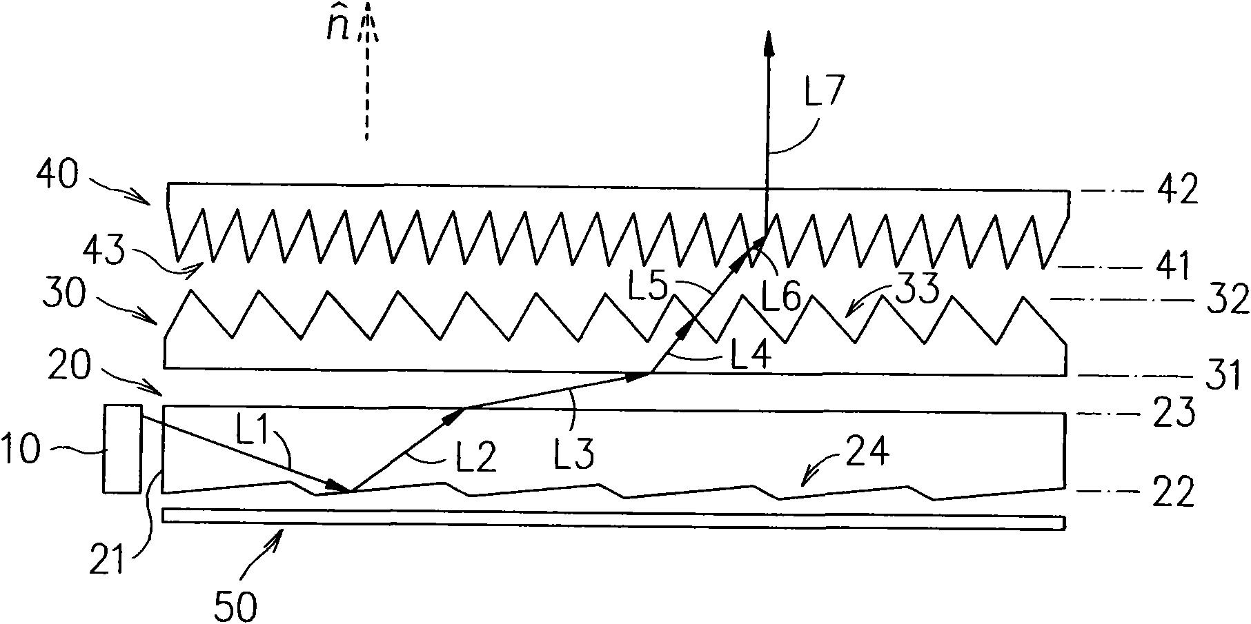
[0055] see figure 1 As shown, the highly collimated surface light source module provided by the present invention mainly includes at least one light source 10 , a light guide plate 20 , a converging film 30 and a straightening film 40 .

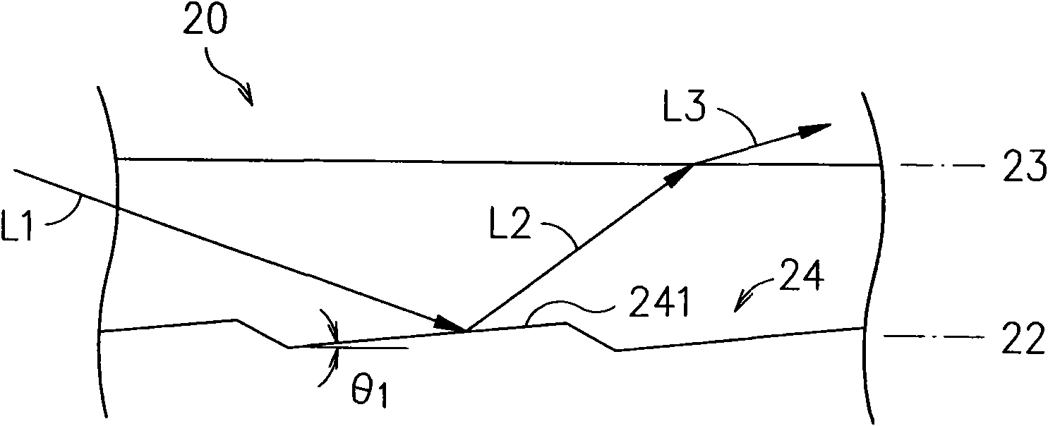
[0056] The light guide plate 20 has at least one side surface 21 , a bottom surface 22 and a top surface 23 . The light source 10 is disposed on the side surface 21 of the light guide plate 20 . The light source 10 can be a light emitting diode (LED) or a cold cathode fluorescent lamp (CCFL) , the light L1 generated by the light source 10 enters the light guide plate 20 from the side surface 21 of the light guide plate 20...


PUM

PropertyMeasurementUnit
Heightaaaaaaaaaa

Abstract

The invention relates to a high-collimation face type light source module and a light output method thereof. The high-collimation face type light source module comprises at least one light source, a light guide plate, a light ray divergence angle convergence diaphragm and a light ray turning collimation diaphragm, wherein the bottom surface or the top surface of the light guide plate, the light output face of the convergence diaphragm and the light input face of the collimation diaphragm are all provided with micro-structures; after the light rays of the light source are emitted into the lightguide plate by the side face of the light guide plate, the light rays are reflected or refracted by the micro-structure of the light guide plate, are guided out of the light guide plate and enter theconvergence diaphragm; the light rays are refracted out of the convergence diaphragm by the micro-structure of the light output face of the convergence diaphragm and enter the collimation diaphragm;after the light rays are refracted by the micro-structure of the light input face of the collimation diaphragm, the light rays are emitted out of the collimation diaphragm by the light output face ofthe collimation diaphragm; therefore, the half-peak full-width number of a light field of the output light can be greatly reduced; and except for high-collimation light output properties, the invention can also be suitable for production and manufacture in the prior back light module technological technology.

Description

technical field [0001] The present invention relates to a high-collimation surface light source module and a light-emitting method thereof, in particular to a light-emitting light field capable of greatly reducing the full width at half maximum (FWHM, Full Width Half Maximum) degree, in addition to having high-collimation light-emitting characteristics , and can also be applied to the high-collimation surface light source module and the light emitting method thereof produced by the existing backlight module technology. Background technique [0002] Liquid crystal displays are widely used, including mobile phones, PDAs, automotive monitors, notebook computers, computer screens, and LCD TVs. However, the TFT-LCD (Thin Film Transistor-Liquid Crystal) display is a non-emission type display. In addition to the liquid crystal panel for controlling image display, an external backlight module is required to provide a flat light source. As for the traditional edge-lit backlight modu...

Claims


Application Information

Patent Timeline
IPC IPC(8): F21V13/00F21V8/00F21V5/00G02F1/13357
Inventor 张延瑜丁嘉仁
Owner IND TECH RES INST
Why Eureka
Try Eureka