
Light guide plate with concave microstructure and manufacturing method thereof

A light guide sheet and microstructure technology, which is applied in the field of light guide sheet, can solve the problems of increasing the thickness of the light guide sheet, difficulty in controlling the direction of light propagation, and the influence of light utilization rate, so as to achieve the effect of improving the utilization rate of light

Inactive Publication Date: 2012-09-19
BRIVU TECH DANYANG
View PDF2 Cites 31 Cited by
  • Summary
  • Abstract
  • Description
  • Claims
  • Application Information

AI Technical Summary

Problems solved by technology

Although the raised scattering points play a very important role in making the light incident from the side into a relatively uniform surface light source, the raised scattering points increase the path of light propagation in the light guide sheet and the thickness of the light guide sheet , and it is difficult to control the propagation direction of the light scattered by the scattering point, so it has a great influence on the utilization rate of light

Method used


Image

  • Light guide plate with concave microstructure and manufacturing method thereof
  • Light guide plate with concave microstructure and manufacturing method thereof
  • Light guide plate with concave microstructure and manufacturing method thereof

Examples


Embodiment Construction

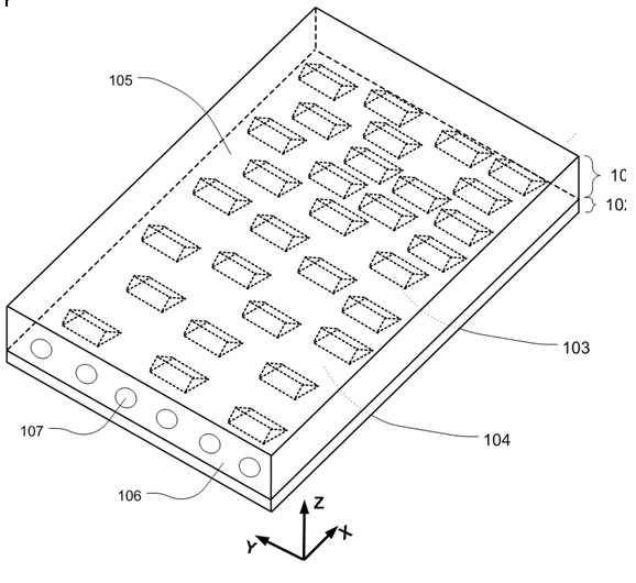
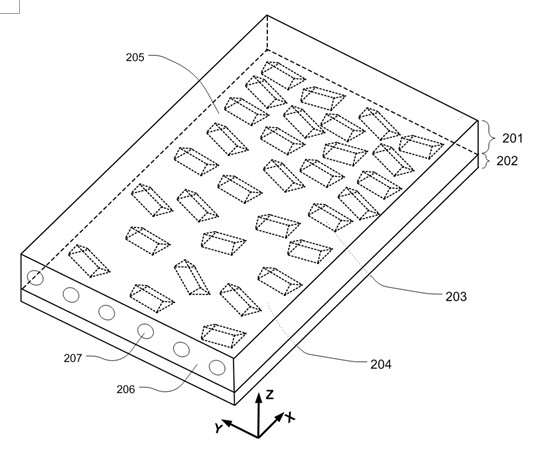
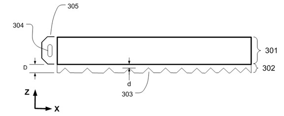
[0028] Depend on figure 1As shown, the light guide sheet of the present invention includes a substrate 101 and a structural layer 102 . The light guide sheet substrate 101 has transparent optical properties. Materials suitable as substrates include polycarbonate (PC), polymethyl methacrylate (PMMA), polyvinyl alcohol (PVA) and polyethylene terephthalic acid (PET). However, the substrate material is not particularly limited. Any material with optically transparent properties can be used as the substrate material. The thickness of the substrate is related to the size and performance of the light source. Generally, the thickness can be in the range of 0.1-10 mm. The light guide substrate 101 includes a -Z surface 104 and a +Z surface 105 parallel to the XY plane, and a light incident surface -X side 106 parallel to the YZ plane. In this example, structural layer 102 is located on the -Z surface of the substrate. The structural layer 102 contains a plurality of recessed micr...


PUM


Abstract

The invention discloses a light guide plate with a concave microstructure and a manufacturing method thereof. The light guide plate comprises a substrate and a structure layer; and the structure layer comprises the concave microstructure with a distance between a surface and a surface of a substrate being less than the thickness of the structure layer. In at least one area in the structure layer of the light guide plate, the positions of the concave microstructure are distributed randomly or according to a set rule, and a density of the concave microstructure is gradually varied along at least one direction. The manufacturing method of the light guide plate disclosed by the invention comprises the steps of: designing a light stopping pattern and distribution thereof; providing a material mixture coating capable of being photopolymerisable on the light guide plate; and using energy radiation to selectively polymerize the material mixture on the coating and remove the non-polymerized material mixture on the coating through a mask board, so that the concave microstructure corresponding to the light stopping pattern and the distribution thereof and the used material mixture is formed by a reserved space of the removed material mixture in the coating. The application range of the light guide plate provided by the invention comprises a backlight source of a liquid crystal display and an LED (Light-Emitting Diode) illumination assembly, so that the light use ratio can be more effectively improved.

Description

technical field [0001] The invention relates to the field of liquid crystal display backlight source and LED lighting, in particular, the invention relates to a light guide sheet used in liquid crystal display backlight source and LED lighting assembly and a manufacturing method thereof. Background technique [0002] There are two types of backlight sources for liquid crystal displays: direct-lit and edge-lit. The direct-lit backlight adopts a method in which a light source, such as an LED, is placed under the liquid crystal panel. Although the direct-type backlight has the advantage of higher light output brightness, it is difficult to achieve thinning due to the limitation of the distance between the light source and the liquid crystal panel required to achieve uniform light distribution. In the edge-lit backlight, the light source is placed on the side of the liquid crystal panel, which is suitable for realizing the thinning of the liquid crystal display. The light guid...

Claims


Application Information

Patent Timeline
IPC IPC(8): G02B6/00G03F7/00
CPCG02B6/00G02B6/0036G02B6/0058G02B6/0065
Inventor 路志坚杨星张亚荣杨云胜
Owner BRIVU TECH DANYANG
Learn More