Light source device and projection system

A light source device and light source technology, applied in the field of projection, to achieve the effect of ensuring uniformity, avoiding spot position deviation, and ensuring that the imaging position remains unchanged

Active Publication Date: 2018-09-25
APPOTRONICS CORP LTD
View PDF21 Cites 30 Cited by
  • Summary
  • Abstract
  • Description
  • Claims
  • Application Information

AI Technical Summary

Problems solved by technology

This concept solves the problem of spot uniformity when the beam enters obliquely and exits obliquely

Method used


Image

  • Light source device and projection system
  • Light source device and projection system
  • Light source device and projection system

Examples


Embodiment 1

[0039] Example part

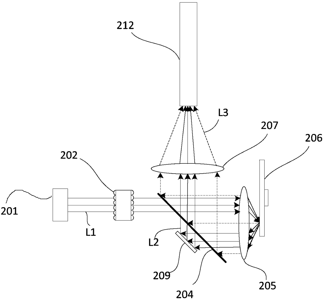
[0040] See image 3 , image 3 It is a schematic structural diagram of a light source device according to Embodiment 1 of the present invention. The light source device includes a first light source 201 , a pair of fly-eye lenses 202 , a light guiding system and a wavelength conversion device 206 , wherein the light guiding system includes a first light splitting component 204 , a collecting lens 205 , a relay lens 207 and an optical path correction component 209 . In addition, the light source device further includes an integrating rod 212 .

[0041] In this embodiment, the first light source 201 emits the first excitation light L1, and the first excitation light L1 is homogenized by the fly-eye lens pair 202 and then enters the light guide system, and is guided to the wavelength conversion device 206 by it. Specifically, the first excitation light L1 is transmitted through the first region of the first light splitting component 204 of the light guidi...

Embodiment 2

[0061] Example two

[0062] See Figure 5 , Figure 5 It is a schematic structural diagram of a light source device according to Embodiment 2 of the present invention. The light source device includes a first light source 201, a pair of fly-eye lenses 202, a light guiding system, and a wavelength conversion device 206, wherein the light guiding system includes a first light splitting component 204, a collection lens 205, a first relay lens 207, and a second relay lens 210, a reflective sheet 208 and an optical path correction component 209a. In addition, the light source device further includes an integrator rod 212 , a filter wheel 211 and a beam angle reflector 214 .

[0063] Compared with Embodiment 1, this embodiment has several differences, and each difference can exist as an independent feature and be combined with Embodiment 1 or other modified embodiments to form an implementable technical solution of the present invention.

[0064] First of all, the first point is...

Embodiment 3

[0076] The third part of the embodiment

[0077] See Figure 7 , is a schematic structural diagram of a light source device according to Embodiment 3 of the present invention. The light source device includes a first light source 201, a pair of fly-eye lenses 202, a light guiding system, and a wavelength conversion device 206, wherein the light guiding system includes a first light splitting component 204, a collection lens 205, a first relay lens 207, and a second relay lens 210, a reflective sheet 208 and an optical path correction component 209b. In addition, the light source device further includes an integrator rod 212 , a filter wheel 211 and a beam angle reflector 214 .

[0078] The difference between this embodiment and the third embodiment lies in that the type and position of the optical path correction component 209b have changed.

[0079] In this embodiment, the optical path correction component 209b is an optical element including a concave reflective surface, ...


PUM


Abstract

The invention provides a light source device. The light source device comprises a first light source, a fly's-eye lens pair, a light guiding system and a wavelength conversion device. The first lightsource emits first exciting light which is subjected to light averaging through the fly's-eye lens pair and then irradiates the light guiding system. The light guiding system guides the first excitinglight to the wavelength conversion device. The wavelength conversion device comprises a wavelength conversion section and a reflection conversion. The wavelength conversion section absorbs the firstexciting light and emits excited light. The first exciting light obliquely irradiates the reflection section and is reflected, so second exciting light is formed. The light guiding system is also usedfor collecting excited light and the second exciting light, and guiding the excited light and the second exiting light to be emitted along an emission light channel. The light guiding system comprises a light path assembly arranged on a second exciting light path used for reflecting the second exciting light and allowing the main optical axis of the second exciting light to coincide with the mainoptical axis of the excited light. The fly's-eye lens pair comprises a first lens array and a second lens array, arranged in the direction of the first exciting light. Lens units for forming the first lens array carry out overlapping imaging on the surface of the wavelength conversion device.

Description

technical field [0001] The invention relates to the field of projection technology, in particular to a light source device and a projection system. Background technique [0002] In the existing projection technology field, it is a commonly used method to use semiconductor blue light laser to excite phosphor powder to generate red light and green light, and to use blue light emitted by semiconductor blue light laser itself, red light and green light to form three primary color light to modulate images. . [0003] In the existing technology, such as figure 1 As shown, the light source device 10 includes a first light source 101, a uniform light device 102, an area beam splitter 103, a collection lens 104, a fluorescent pink wheel 105, a first relay lens 106 and a second relay lens 108, a reflector 107 and a square Stick 109. [0004] The first light source 101 is a blue laser, and the blue excitation light emitted by it is homogenized by the homogenization device 102 , and ...

Claims


Application Information

Patent Timeline
Patent Type & Authority Applications(China)
IPC IPC(8): G03B21/20
CPCG03B21/204G03B21/2066G03B21/208G03B33/08G02B27/123H04N9/3152H04N9/3158
Inventor 郭祖强杜鹏李屹
Owner APPOTRONICS CORP LTD
Why Eureka
Try Eureka