Method and an apparatus for monitoring and controlling flows

a flow monitoring and flow control technology, applied in the field of medical equipment, can solve the problems of measurement results deviating from the true values, affecting the accuracy of mechanical ventilation control, so as to ensure the accuracy and safety of controlling mechanical ventilation and accurate flow monitoring and control

Active Publication Date: 2007-07-19
SHENZHEN MINDRAY BIO MEDICAL ELECTRONICS CO LTD
View PDF10 Cites 88 Cited by
  • Summary
  • Abstract
  • Description
  • Claims
  • Application Information

AI Technical Summary

Benefits of technology

[0012]In view of the above described deficiencies of the prior art, it is an object of the present invention to provide an improved method and apparatus for monitoring and controlling flows in medical equipment including anesthetic mac

Problems solved by technology

However, the same fact that the measuring point is located near the respiratory tract of the patient also produces unfavorable effect, because in this case the flow sensor is affected easily by the secretions of the respiratory tract of the patient and the water vapor condensate in the respiratory conduit such that the measured results may deviate from the true values and that the ventilation control may be disabled.
However, since it is the flow of the drive gas that is measured, which is influenced by the leakage from conduits and the change of compliance, this measured flow deviates from the actual ventilation volume in certain degree.
Moreover, this deviation can not be compensated because the amount of the leakage and the extent of the change of compliance in the breathing circuit can not be monitored.
In addition, with respect to the realization of some respiratory functions, flow speed trigger and the like can not be realized because the flow sensor is located far away from the patient end.
As a result, the distal end monitoring is vanishing from the market.
Regardless of a patient end flow monitoring or an anesthetic ventilator end flow monitoring, this control mode has a serious defect.
When the measured value of the flow sensor largely deviates from the preset value, there is no way to determine the causes for the deviation, for example, whether it is caused by the inaccurate measurements of the flow sensor or resulted from changes in the characteristics of the inhalation valve.
In this way, the user is unable to find out the deviation in the sensor measurements.
As a further result, the actual ventilation volume supplied to the patient is not consistent with the predetermined volume and so it is not possible to ensure the safety of the mec

Method used


Image

  • Method and an apparatus for monitoring and controlling flows
  • Method and an apparatus for monitoring and controlling flows
  • Method and an apparatus for monitoring and controlling flows

Examples


Embodiment Construction

[0028]The present invention will be described hereunder in further details with reference to the preferred embodiments shown in the accompanying drawings.

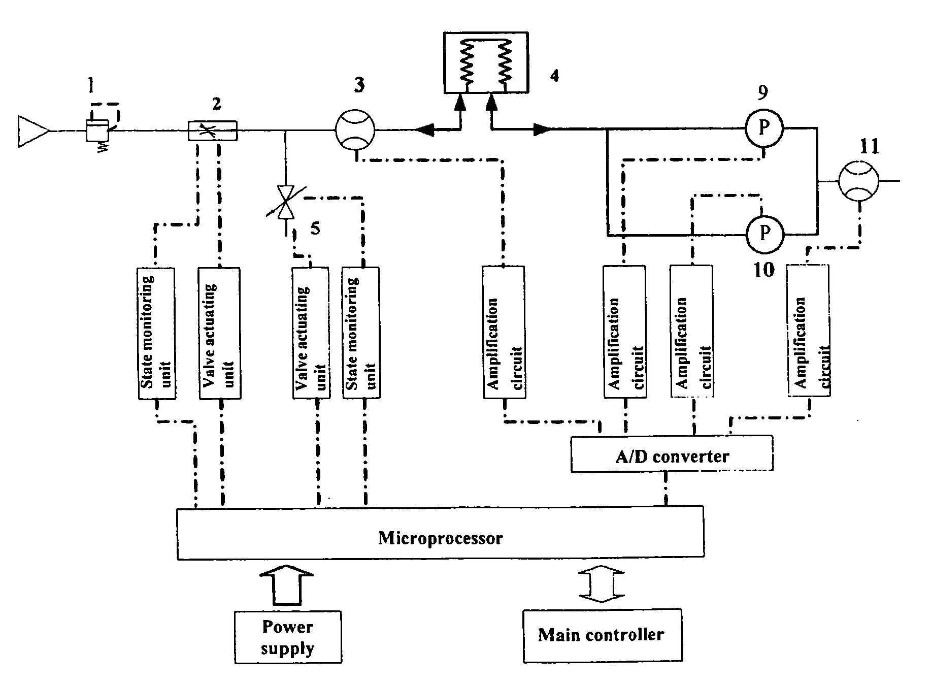
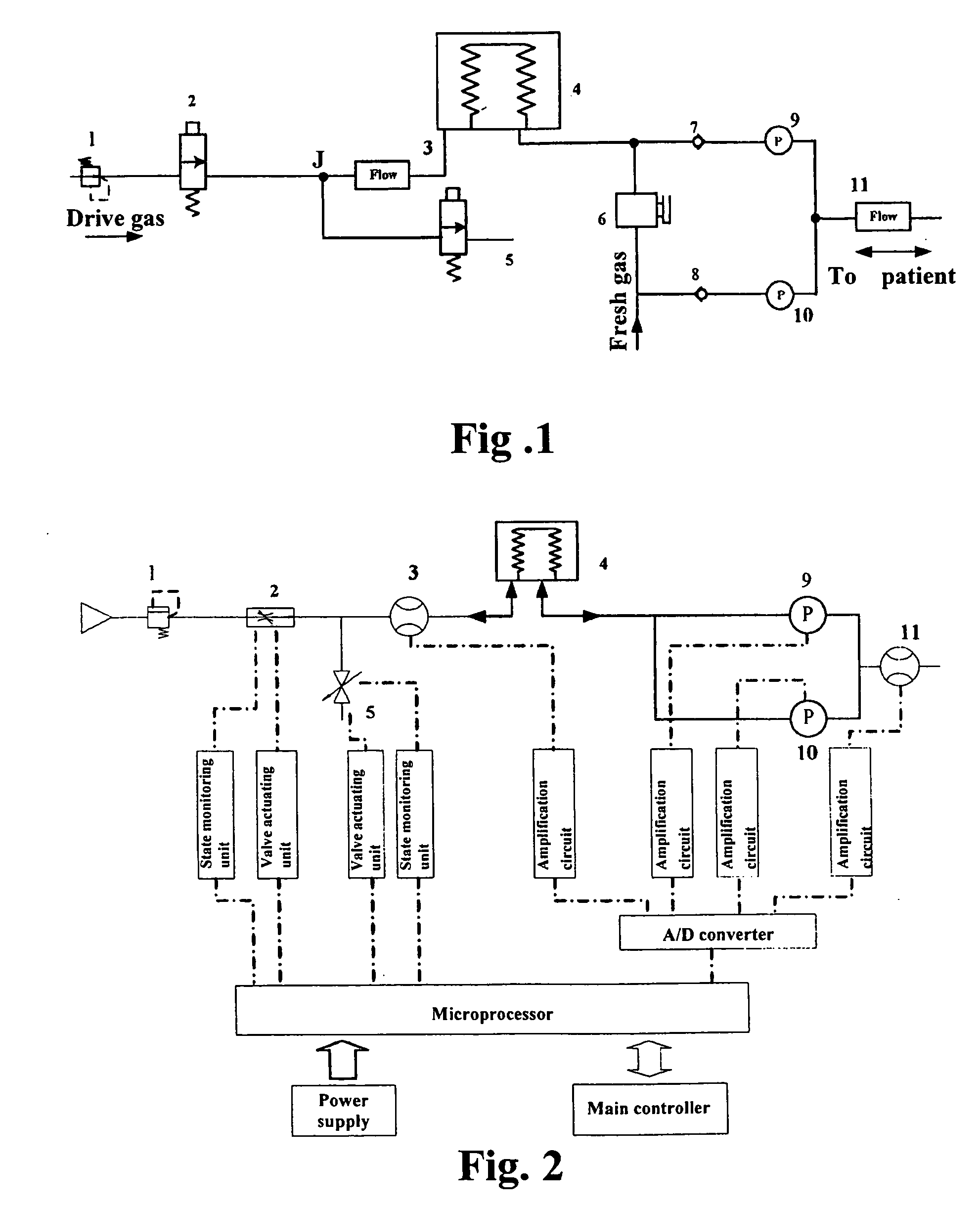
[0029]As shown in FIG. 2, the apparatus for monitoring and controlling flows according to the present invention comprises a power supply, a microprocessor, an airway system, and several microprocessor-controlled valve state monitoring units, valve actuating units and data collecting and receiving units. The apparatus may further comprise microprocessor-controlled interface units for connecting a main controller (also known as a higher level controller). As shown in FIG. 1, the airway system comprises a bellows 4 and drive gas conduits at the ventilator end and breathing tubing at the patient end which are connected to the outer chamber and the gasbag of the bellows 4, respectively. The drive gas conduits connect a pressure-reducing valve 1, an inhalation valve 2 and an exhalation valve 5 which is used to vent the gas. The inhalatio...


PUM


Abstract

A method and an apparatus for monitoring and controlling flows in medical equipment including an anesthetic machine and a ventilator for influencing a patient's respiratory system are disclosed. The apparatus comprises a microprocessor and an airway system comprising drive gas conduits provided with an inhalation valve (2) and an exhalation valve (5) for gas discharging as well as a ventilator end flow sensor (3) for measuring the introduced or discharged drive gas flow through the valves. The airway system also comprises patient end breathing tubing in which a patient end flow sensor (11) for measuring the patient's inspired and expired gas flow is provided. By comparing the measured values of the two flow sensors against the characteristic curve of the inhalation valve (2), the microprocessor can judge the operation states and accuracy of the respective flow sensors and the inhalation valve (2).

Description

STATEMENT OF RELATED APPLICATION[0001]The present application claims the priority of the Chinese Patent Application No. 200610032990.2, filed on Jan. 13, 2006, entitled “A Method and an Apparatus for Monitoring and Controlling Flows”, which is incorporated herein by reference in its entirety.FIELD OF THE INVENTION[0002]The present invention relates to medical equipment, and more particularly to a method and an apparatus for monitoring and controlling flows in medical equipment that influence a patient's respiratory system by processing the gas.BACKGROUND OF THE INVENTION[0003]An anesthetic machine is auxiliary equipment for guiding a patient to inhale anesthetic gas and for mechanical ventilation during an operation. Flow and airway pressure are the most basic parameters which the anesthetic machine monitors, and the calculation of other parameters or even the whole mechanical ventilation process control is based thereon. Therefore, the precision and stability in measuring and testi...

Claims


Application Information

Patent Timeline
IPC IPC(8): A61M15/00A61M16/00
CPCA61M16/00A61M16/0081A61M2016/0036A61M16/0051A61M16/024
Inventor LI, XINSHENGZHOU, XIAOYONG
Owner SHENZHEN MINDRAY BIO MEDICAL ELECTRONICS CO LTD
Why Eureka
Try Eureka