Display device for working machine

a display device and working machine technology, applied in the field of display devices, can solve the problems of poor visibilities and the operator cannot concentrate on the driving control of the working machine, and achieve the effects of reducing the visibilities of indication marks, reducing individual sizes, and large display devices

Inactive Publication Date: 2007-07-26
KOMATSU LTD
View PDF22 Cites 42 Cited by
  • Summary
  • Abstract
  • Description
  • Claims
  • Application Information

AI Technical Summary

Benefits of technology

[0025] The invention has been conceived in view of the practical situation and has a first object to make it possible to display both a state indication mark and a state change indication mark on a common display screen of a limited area without reducing their individual sizes even if their numbers increase, thereby to make neither a large size of the display device nor a reduction in the visibilities of the indication marks and to cause no trouble in the driving control of a working machine such as a construction machine.

Problems solved by technology

However, a plurality of state indication marks are displayed on the display screen so that the numerical values or letters are so small on the display screen of the limited area as to cause poor visibilities.
Therefore, the operator has to gaze at those numerical values or letters to raise a problem that the operator cannot concentrate on the driving control of the working machine such as the construction machine.

Method used


Image

  • Display device for working machine
  • Display device for working machine
  • Display device for working machine

Examples


first embodiment

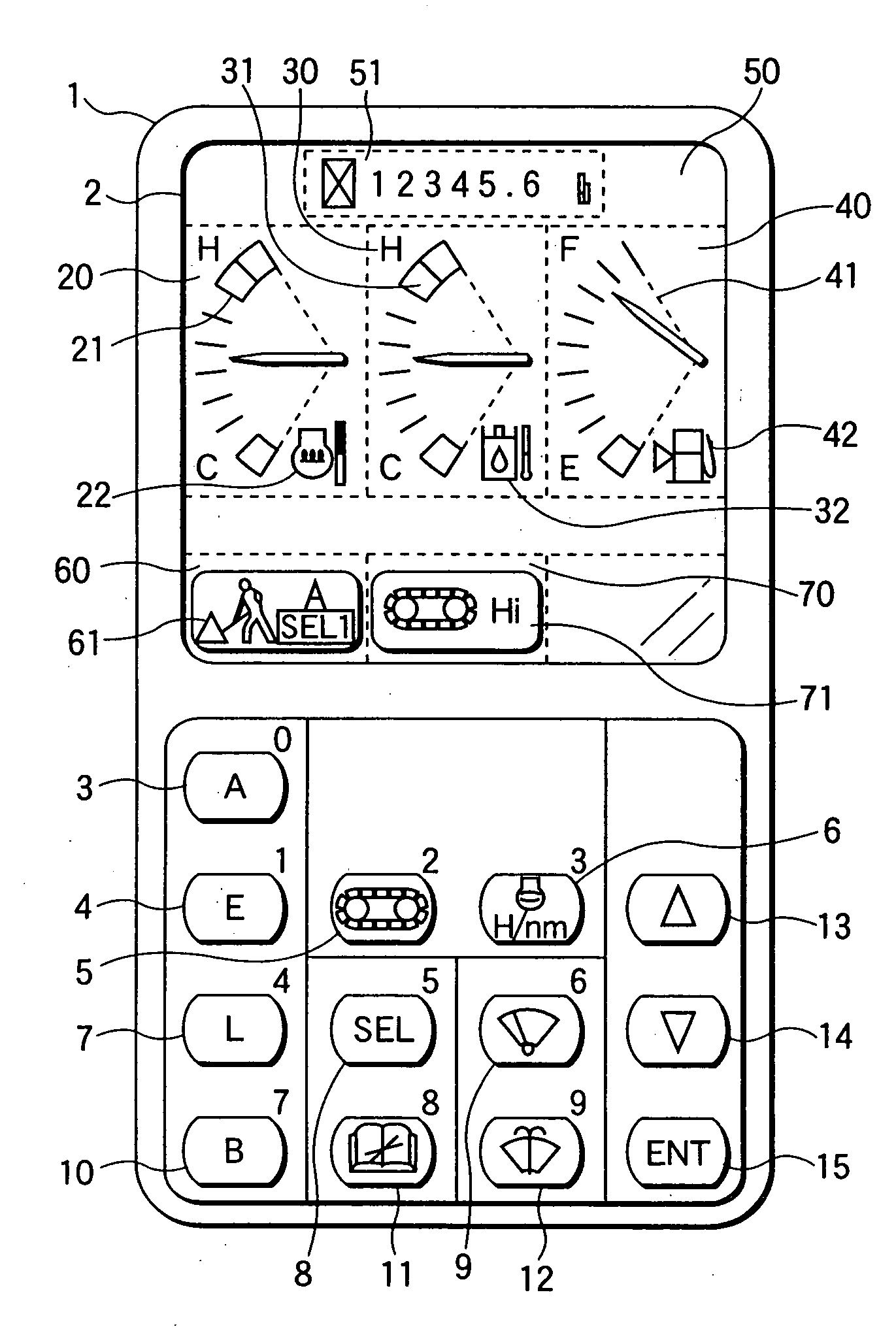
[0106] A display device for a working machine according to the invention will be described on a monitor panel to be used in a hydraulic shovel with reference to the accompanying drawings.

[0107] Here in this embodiment, the state change indication mark to be displayed on the display screen is preferably exemplified by a caution mark to be displayed where an abnormality occurs.

[0108] The hydraulic shovel is provided with a running equipment including a running control lever, a running hydraulic motor and a crawler. When the running control lever is controlled, more specifically, the running hydraulic motor is activated according to the control of the running control lever so that the crawler connected to the running hydraulic motor is driven according to the activation of the running hydraulic motor. On the other hand, the hydraulic shovel is provided with a working equipment including a working machine control lever, a working machine hydraulic cylinder and a working machine (e.g.,...

second embodiment

[0161] Next, a second embodiment will be described with reference to FIGS. 9A and 9B.

[0162] In the second embodiment, the display device of the working machine according to the invention will be described on a monitor panel which is employed in an arm crane having a hook attached to the bucket portion of the hydraulic shovel, with reference to the accompanying drawings.

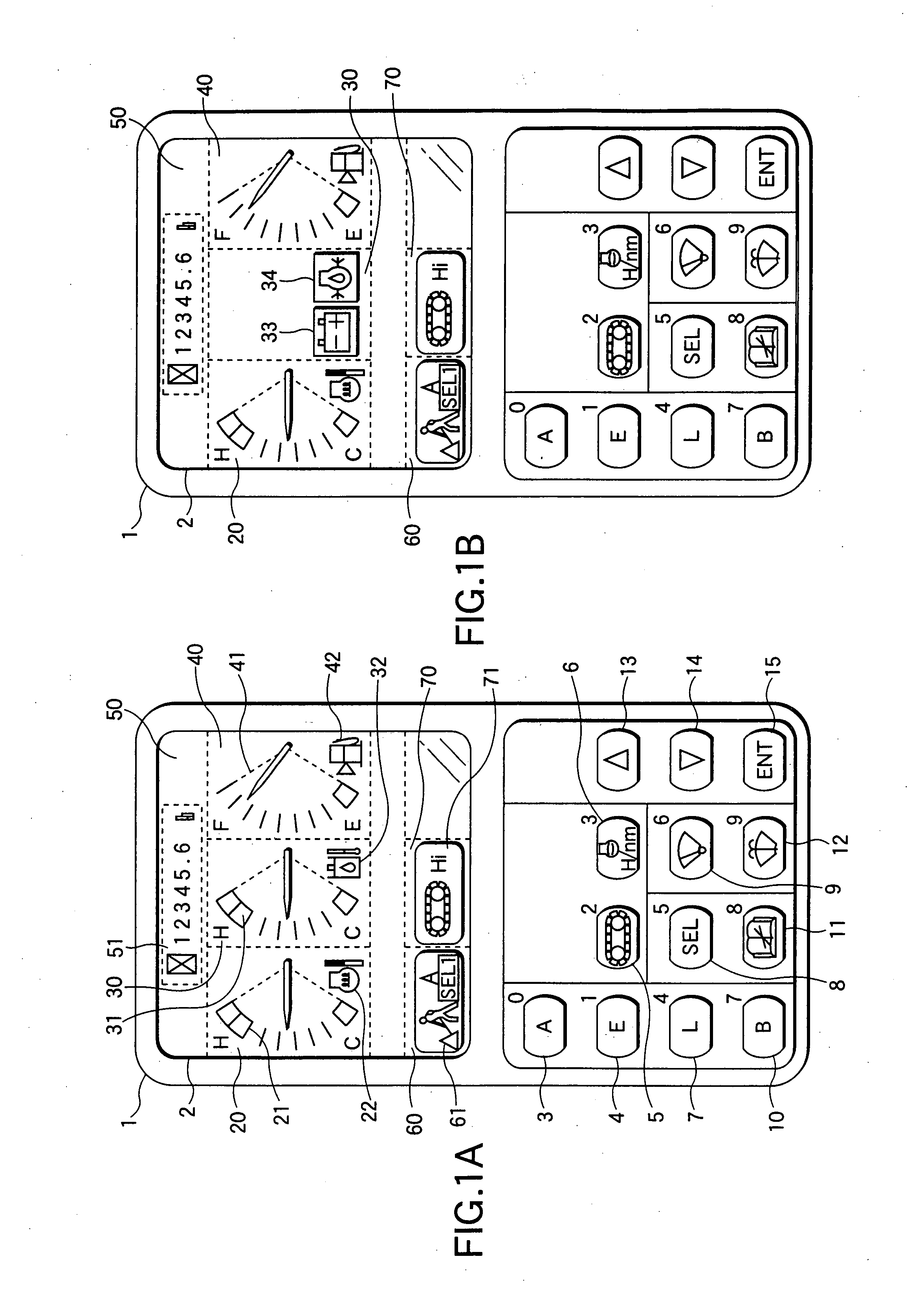
[0163]FIG. 9A is a view showing the display screen before switches are depressed, and FIG. 9B is a view showing the display screen after the switches were depressed.

[0164] Here, the screen construction of the display screen 2 shown in FIGS. 1A and 1B to FIG. 7 is different from that of the display screen 2 shown in FIGS. 9A and 9B. Of the individual state indication marks shown in FIGS. 9A and 9B, the same state indication marks as those shown in FIGS. 1A and 1B to FIG. 7 will be described by designating them by the common reference numerals.

[0165] On the display screen 2, there are displayed the state indication m...

third embodiment

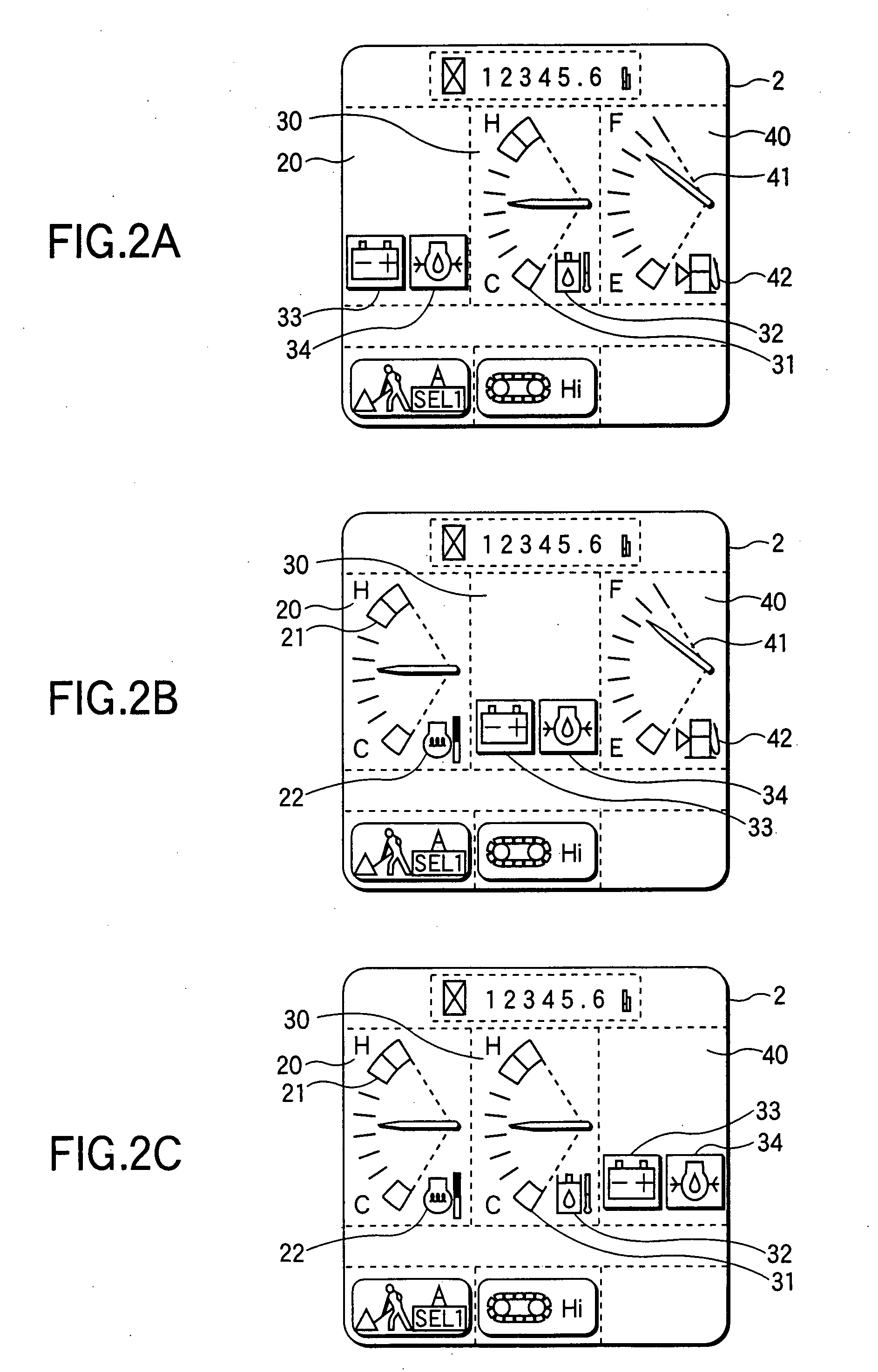
[0182] Next, a third embodiment will be described with reference to FIGS. 10A and 10B and FIGS. 11A and 11B.

[0183]FIG. 10A is a view showing the display screen before a predetermined abnormality occurs, and FIG. 10B is a view showing the display screen after the predetermined abnormality occurred.

[0184] If the battery voltage drops where the display screen 2 is in the state shown in FIG. 10A, there are reduced and displayed the working oil temperature indication mark 31 and the working oil temperature caution mark 32 which have been displayed in the display segment 92. Moreover, the battery caution mark 33 is displayed in that portion of the display segment 92, in which the working oil temperature indication mark 31 is reduced.

[0185]FIG. 11A is a view showing the display screen before a predetermined abnormality occurs, and FIG. 11B is a view showing the display screen after the predetermined abnormality occurred.

[0186] If the battery voltage drops where the display screen 2 is i...


PUM


Abstract

The invention is directed to a display device for working vehicle, which is adapted so that additional information can be displayed. In the invention, display indication marks of the two types can be interchangeably displayed on a common display screen of a limited area without reducing the sizes of the individual marks, so that neither a larger size of a display device nor a drop in the visibility of the indication marks is necessary. This enables the driver to control a working machine such as a construction machine and have additional information about the construction machine without any trouble in the driving.

Description

CROSS REFERENCE TO RELATED APPLICATIONS [0001] This application is a divisional application of U.S. patent application Ser. No. 09 / 920,736, filed on Aug. 3, 2001, which is incorporated herein by reference and which is based on and incorporates herein by reference Japan patent application No. 2000-238608, filed Aug. 7, 2000, and Japan patent application No. 2001-137701, filed May 8, 2001.BACKGROUND OF THE INVENTION [0002] 1. Field of the Invention [0003] The present invention relates to a display device which is mounted in the cabin of a working machine for displaying the state and change of the working machine. [0004] 2. Related Art [0005] The construction machine is provided in its cabin with a display device for indicating the state of the construction machine such as a cooling water temperature and an abnormality such as a drop in an engine oil pressure. The display device of the prior art will be described with reference to FIG. 8. [0006] On the display screen 81 of a display de...

Claims


Application Information

Patent Timeline
Patent Type & Authority Applications(United States)
IPC IPC(8): G08B21/00B60Q1/00G08B3/00E02F9/26G09F9/00
CPCB60K37/02E02F9/26B60K2350/1072B60K2370/155
Inventor SHIMAZU, MITSUHIROKOORIYAMA, KENJI
Owner KOMATSU LTD
Why Eureka
Try Eureka