Liquid crystal lens and imaging lens device

a liquid crystal lens and imaging lens technology, applied in non-linear optics, instruments, optics, etc., can solve the problems of reducing the response difficult to produce a smooth distribution of the refractive index in the liquid crystal layer, and degradation of the lens performance of the liquid crystal lens

Inactive Publication Date: 2007-09-20
CITIZEN WATCH CO LTD
View PDF5 Cites 77 Cited by
  • Summary
  • Abstract
  • Description
  • Claims
  • Application Information

AI Technical Summary

Benefits of technology

[0038] When the liquid crystal lens functions as a diffractive optical element, it is preferable that the lens has a positive power. A diffractive optical element generally has an inverse dispersion characteristics as compared to a common refractive lens. Thus, when a liquid crystal lens that functions as a diffractive optical element has a positive lens power, the color aberration of a refractive lens having the similar positive lens power is cancelled so that the color aberration of the lens system including the liquid crystal lens can be advantageously corrected.
[0039] In the liquid crystal lens used in the imaging lens device according to the present invention, it is preferable that the first transparent substrate has a member with a Fresnel lens surface formed thereon. The first transparent substrate further comprises a flat plate-shaped substrate, and the first electrode is preferably disposed between the flat plate-shaped substrate and the member. By disposing the electrode between the flat plate-shaped substrate and the member having a Fresnel lens surface formed thereon, the electrode can be formed on a smooth surface so that line breakage and disturbance of orientation due to transverse electric field applied to the liquid crystal near the Fresnel lens surface which may arise when the electrode is formed on the Fresnel lens surface can be prevented.

Problems solved by technology

However, with the focusing mechanism as disclosed in Patent Reference 1, it is difficult to produce a smooth distribution of refractive index in the liquid crystal layer since the zonal electrode has non-uniform structure.
In addition, the zonal electrode itself gives rise to diffraction and scattering of the light incident upon the liquid crystal lens, which also lead to degradation of the lens performance of the liquid crystal lens.
However, as the liquid crystal layer is thick, the response performance of the liquid crystal lens decreases and the manufacture of the liquid crystal lens becomes more difficult.
Therefore, application of a conventional liquid crystal lens has been limited to an auto-focus function.
Thus, when a liquid crystal lens is to be employed in a camera module for a mobile phone for which a low profile is required, the optical path length becomes too large for a camera module of low profile.
In addition, the maximum lens power of a liquid crystal lens cannot be adequately increased, and therefore, focusing range is limited.
Thus, if the lens power of a liquid crystal lens included in the imaging lens is changed for focusing, an aberration such as an astigmatism, curvature of field, etc. becomes large, leading to a degraded resolution of the imaging lens.

Method used


Image

  • Liquid crystal lens and imaging lens device
  • Liquid crystal lens and imaging lens device
  • Liquid crystal lens and imaging lens device

Examples


first embodiment

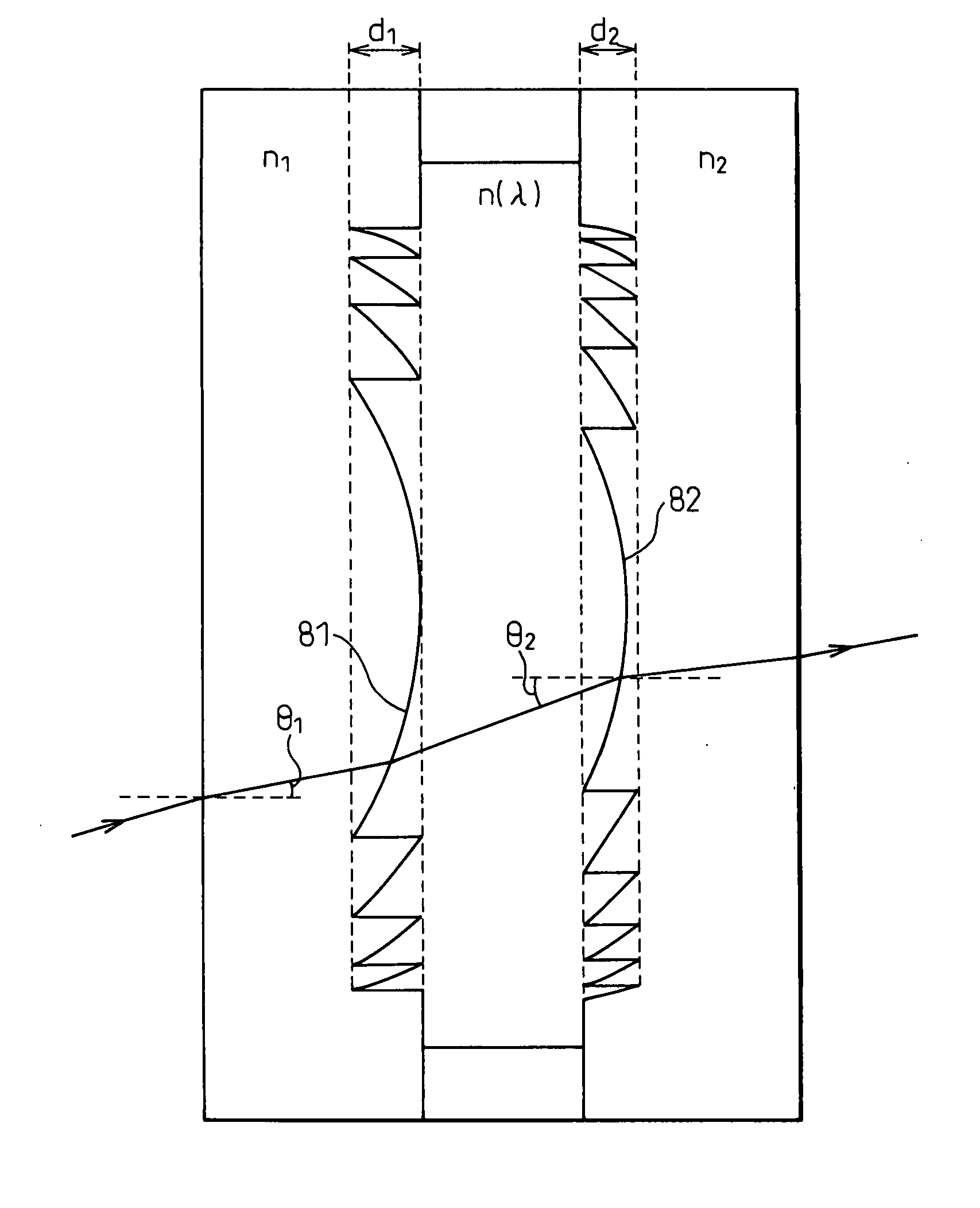
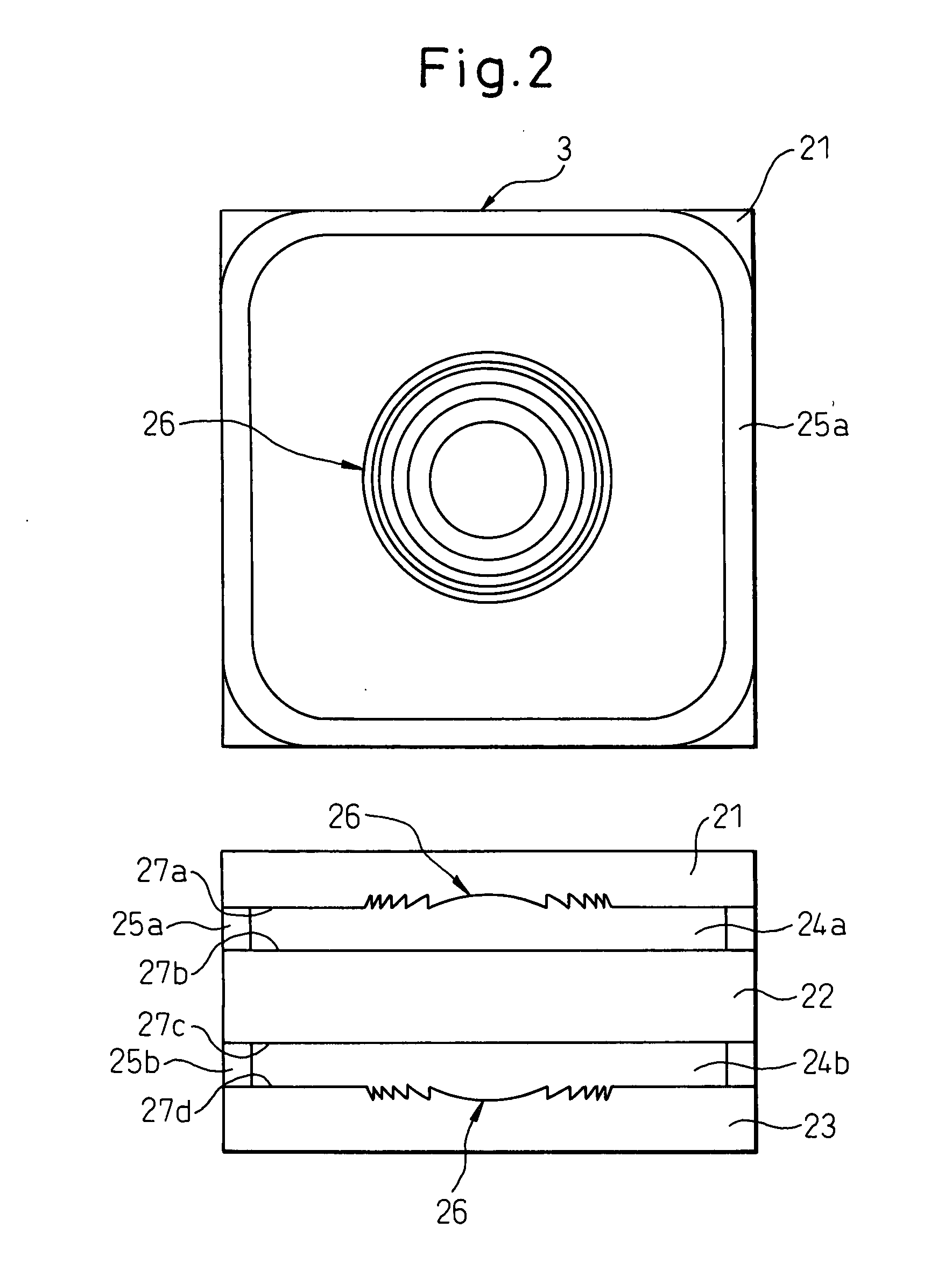
[0085] As described above, in accordance with the present invention, the step difference between zones of the Fresnel lens surface 26 provided on the boundary of the liquid crystal layers 24a, 24b and the transparent substrates 21, 23 of the liquid crystal lens 3 of variable lens power used in focusing, is set such that, at generally minimum lens power (that is, generally minimum refractive index of the liquid crystal layer 24a, 24b for extraordinary ray) of the liquid crystal lens 3, the difference of the optical path length at the step is an integer multiple of the wavelength of incident light, especially an integer multiple of any of the wavelength for which the imaging element has sensitivity. With such a construction, it is also possible to impart the function of a diffractive optical element to the liquid crystal lens 3, while the interference of luminous flux from zones of the Fresnel lens surface 26 can be prevented even when the lens power of the liquid crystal lens 3 is ch...

second embodiment

[0100] As described above, in accordance with the present invention, the step difference between zones of the Fresnel lens surface 26 provided on the boundary of the liquid crystal layers 24a, 24b and the transparent substrates 21, 23 of the liquid crystal lens 13 of variable lens power used in focusing, is set such that the optical path difference produced at the step for ordinary ray is an integer multiple of design wavelength, preferably one design wavelength, of the incident light. For an extraordinary ray, the refractive index of the liquid crystal layers 24a, 24b is changed within such range that optical path difference produced at the step is greater than the design wavelength of the incident light. With such construction, the liquid crystal lens 13 can also function as a diffractive optical element over the entire range of variable lens power. As a result, the imaging lens device 11 can have a wide focusing range and exhibit good image-forming performance over the entire foc...


PUM

PropertyMeasurementUnit
refractive indexaaaaaaaaaa
wavelengthaaaaaaaaaa

Abstract

The present invention provides an imaging lens device, which has a widely extended focusing range and exhibits good resolution over the entire focusing range. The imaging lens device comprises a liquid crystal lens for focusing an object at a prescribed distance, comprising a liquid crystal layer, a first transparent substrate disposed adjacent to one surface of the liquid crystal layer and having a first electrode and having Fresnel lens surface formed on the boundary with the liquid crystal layer, a second transparent substrate disposed adjacent to the other surface of the liquid crystal layer and having a second electrode; a controller for changing the refractive index of the liquid crystal layer for extraordinary ray by changing electric voltage applied between the first electrode and the second electrode; and an imaging element for taking an image of the object. The liquid crystal lens functions as a diffractive optical element for an extraordinary ray when the liquid crystal layer has a prescribed refractive index for an extraordinary ray incident upon the liquid crystal layer.

Description

CROSS REFERENCE TO RELATED APPLICATIONS [0001] The Applicant claims the right of priority based on Japanese Patent Application JP 2006-54668, filed on Mar. 1, 2006, and Japanese Patent Application JP 2006-241180, filed on Sep. 6, 2006, and the entire contents of JP 2006-54668 and JP 2006-241180 are hereby incorporated by reference. FIELD OF THE INVENTION [0002] The present invention relates to a liquid crystal lens and an imaging lens device, and more particularly to an imaging lens device using a liquid crystal lens as a variable focus lens. BACKGROUND OF THE INVENTION [0003] Recently, a mobile phone handset equipped with a digital camera (hereinafter referred to as a mobile camera phone) has become more and more prevalent. From the viewpoint of mobility, it is desirable to have a mobile phone that is of small size and light weight, as well as of low profile. Therefore, it is required that an imaging lens device mounted on a mobile camera phone also be small and light weight, as we...

Claims


Application Information

Patent Timeline
Patent Type & Authority Applications(United States)
IPC IPC(8): G02F1/13
CPCG02F1/13306G02F1/133526G02F2001/294G02F1/29G02F1/1347G02F1/294
Inventor MATSUMOTO, KENJI
Owner CITIZEN WATCH CO LTD
Why Eureka
Try Eureka