Vacuum feeding joint

a vacuum feeding and valve technology, applied in the direction of hose connections, branching pipes, mechanical equipment, etc., can solve the problem of difficult to smoothly rotate the rotating table at a precise rotating angle, and achieve the effect of air tightness in the communication passage and effective supply of vacuum

Inactive Publication Date: 2008-01-17
KOGANEI
View PDF3 Cites 4 Cited by
  • Summary
  • Abstract
  • Description
  • Claims
  • Application Information

AI Technical Summary

Benefits of technology

[0011]According to the present invention, since the seal members during the stop of the vacuum feeding are away from at least one of the rotated surface and the fixed surface and no friction occurs, a loss of a rotational driving force of the rotating body is reduced and a smooth rotation thereof can be made at a precise rotating angle.
[0012]According to the present invention, since the seal members during the vacuum feeding contact with the rotated surface and the fixed surface to seal the gap th

Problems solved by technology

However, if the seal members are thus mounted, friction is caused in rotate-driving the rotating

Method used


Image

  • Vacuum feeding joint
  • Vacuum feeding joint
  • Vacuum feeding joint

Examples


Embodiment Construction

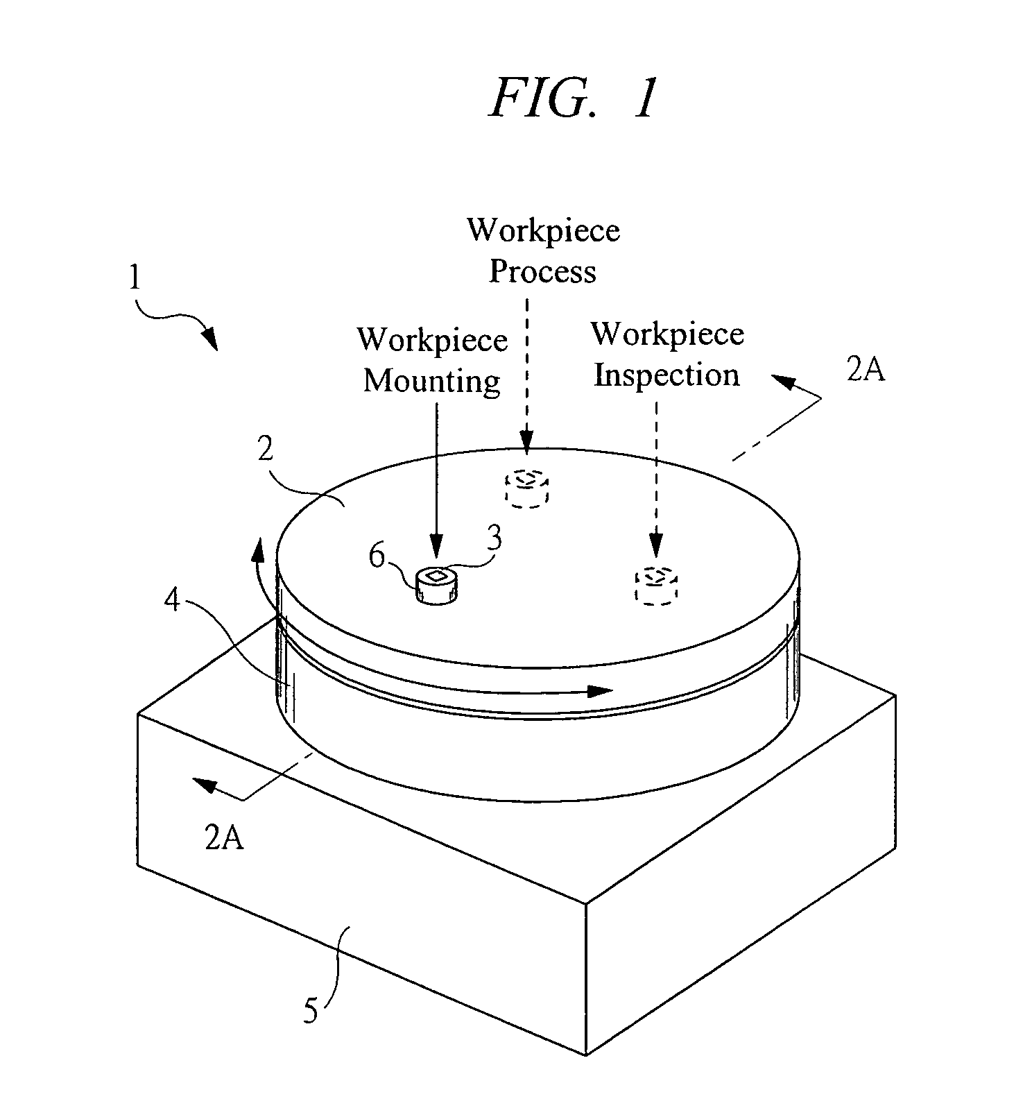
[0026]FIG. 1 is a perspective view showing a workpiece conveyance table provided with a vacuum feeding joint according to an embodiment of the present invention. A workpiece conveyance table 1 carries, by rotating a rotating table 2 serving as a rotating body, a fine workpiece 3 such as a semiconductor chip mounted on an upper surface thereof up to a target position such as a workpiece inspecting position and a workpiece processing position, wherein it includes: the rotating table 2 on which a workpiece bench 6 serving as an air adsorption section is provided; a fixed base 4 on which the rotating table 2 is rotatably mounted; and a support 5 for supporting the fixed base 4 from below.

[0027]The fine workpiece 3 is mounted on the upper surface of the work bench 6 by an external conveyance device unshown and is carried up to the above predetermined position by rotating the rotating table 2 using a drive unit unshown. The fine workpiece 3 is not adsorbed to the work bench 6 when being r...


PUM


Abstract

A rotating table provided with a determined gap Db and serving as a rotating body is rotatably mounted on a fixed base. Seal-member accommodating spaces serving as annular grooves are partitioned and formed in a fixed surface. Annular seal members are disposed in the seal-member accommodating spaces. When a vacuum is supplied to a communication passage, the absorbed seal members contact with the fixed surface and a rotated surface to seal gaps therebetween. When a positive pressure is supplied to the communication passage, the seal members are relocated in the seal-member accommodating spaces. The seal-member accommodating space has a taper portion, thereby preventing the seal members from biting. While the rotating table is being rotatably driven, no vacuum is supplied to the communication passage.

Description

TECHNICAL FIELD[0001]The present invention relates to a vacuum feeding joint for supplying a vacuum between a fixed base and a rotating body rotatably mounted thereon.BACKGROUND ART[0002]Some of conveyance devices for precise fine workpieces such as semiconductor chips are of a type which mounts the fine workpieces on an upper surface of a rotating table serving as a rotating body to convey them up to a target position and concurrently exerts their processes or inspections in each mounting state. Thereamong, a vacuum feeding joint, in which an air adsorption section is provided on the upper surface of the rotating table and a vacuum feeding source is connected to the fixed base supporting the rotating table, is known as the above-described conveyance device capable of mounting the fine workpieces on the upper surface of the rotating table with high precision. In the vacuum feeding joint, a communication passage for communicating with the air adsorption section and the vacuum feeding...

Claims


Application Information

Patent Timeline
IPC IPC(8): F16L27/00H01L21/00
CPCH01L21/67126H01L21/68
Inventor FUJIWARA, TERUHIKO
Owner KOGANEI
Why Eureka
Try Eureka