

Portable terminal
a terminal and portability technology, applied in the field of portability terminals, can solve problems such as unattractive terminal appearance, and achieve the effect of preventing foreign materials from entering the terminal and attractive terminal design
- Summary
- Abstract
- Description
- Claims
- Application Information
AI Technical Summary
Benefits of technology
Problems solved by technology
Method used
Image

Examples
Embodiment Construction
[0036]Description will now be given in detail of the exemplary embodiments of the present invention, with reference to the accompanying drawings. Wherever possible, the same reference number has been used for the same part in all of the exemplary embodiments.
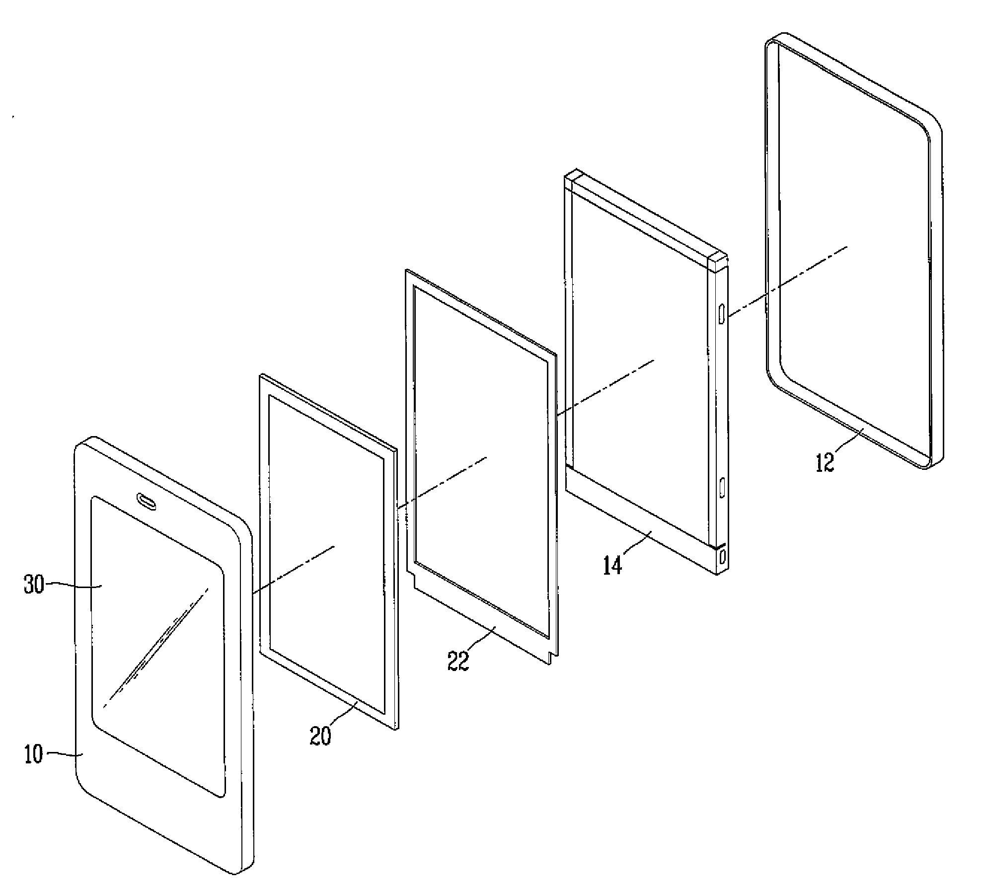
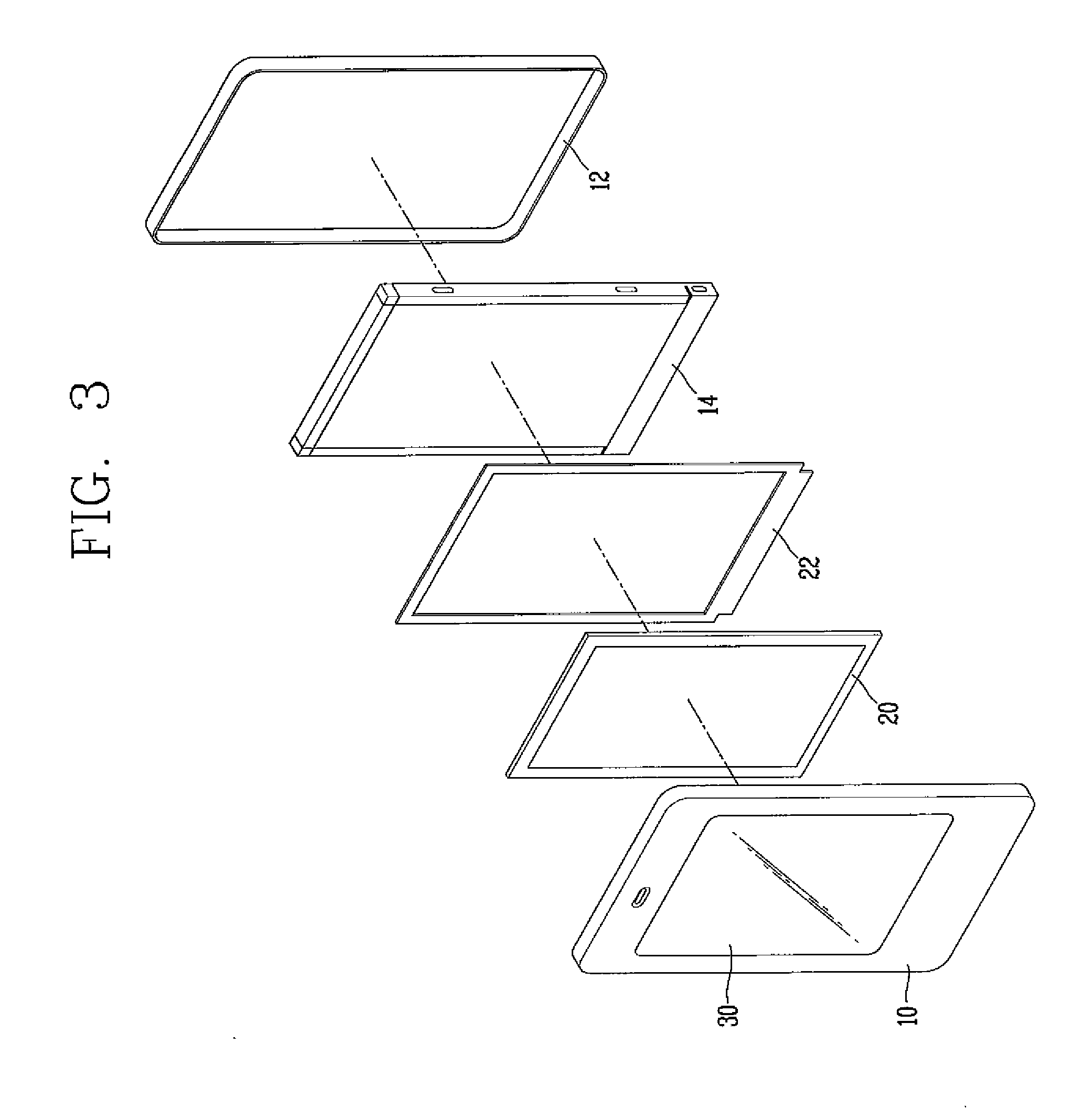
[0037]As seen in FIGS. 3 and 4, a portable terminal, such as, but not limited to a mobile communication device, in accordance with the first exemplary embodiment of the present invention includes bodies 10 and 12, a display 14 which is disposed in the bodies 10 and 12 to display information, and a transparent touch pad 20 which is disposed at an upper surface of the display 14 to input information in a capacitive manner.
[0038]Inside the bodies 10 and 12, a main circuitry supporting substrate (not shown) electrically connected to both the display 14 and the touch pad 20, and a battery for supplying power source may further be disposed.
[0039]When the portable terminal is used in a communication mode, both a speaker for outputting ...
PUM
 Abstract
Description
Claims
Application Information