
Antenna device for portable terminal

a portable terminal and antenna device technology, applied in the direction of non-resonant long antennas, non-interfering antenna combinations, collapsible antenna means, etc., can solve the problems of inconvenient carrying of the terminal b>1/b> in a bag, pocket, damaged parts, etc., to prevent damage and attractive terminal design

Inactive Publication Date: 2007-04-12
SAMSUNG ELECTRONICS CO LTD
View PDF4 Cites 5 Cited by
  • Summary
  • Abstract
  • Description
  • Claims
  • Application Information

AI Technical Summary

Benefits of technology

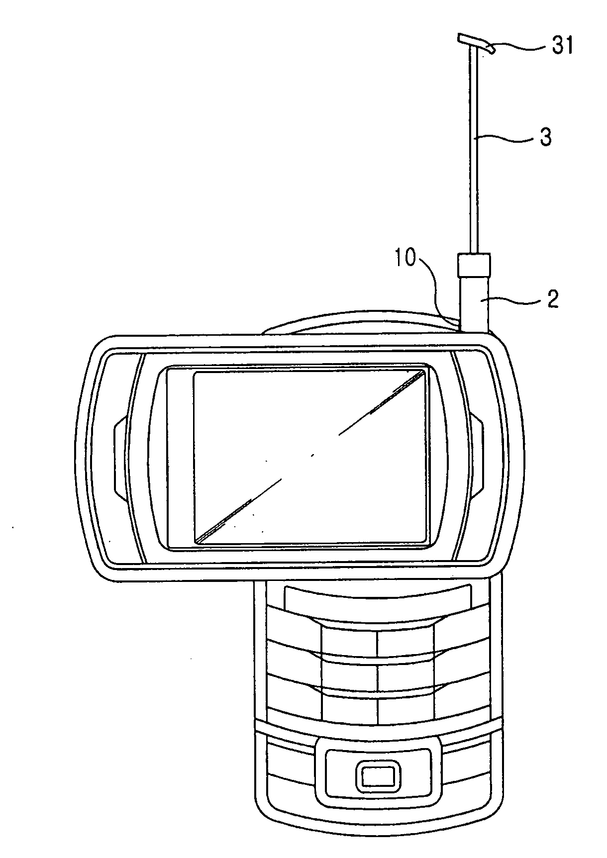
[0019] Accordingly, the present invention has been made to solve the above-mentioned problems occurring in the prior art. An object of the present invention is to provide an antenna device for a portable terminal, which allows a whip antenna and helical antenna of a terminal to be retracted / withdrawn along an extension from the terminal, while not causing them to protrude from the terminal, such that an attractive design of the terminal can be obtained and the antenna can be prevented from being damaged by external impacts.
[0020] Another object of the present invention is to provide an antenna device for a portable terminal, which is retracted / withdrawn along an extension from a terminal, so that an antenna for exclusive use in the broadcasting service can have improved portability.

Problems solved by technology

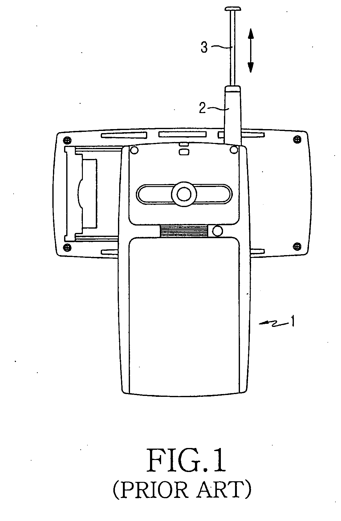
Therefore, there are disadvantages in that the helical antenna 2 may be broken due to the retraction / withdrawal of the whip antenna 3.
It is also inconvenient to carry the terminal 1 in a bag, pocket, etc. due to the helical antenna 2 protruding out of the terminal.
Additionally, such a protruding portion may be damaged and broken if a user drops the terminal, and such an antenna makes it impossible to obtain an attractive design for the terminal.
However, a conventional antenna for exclusive use in the broadcasting service is inconvenient to use, because it is too bulky when fixed to a terminal to permit the enjoyment of radio and TV services.
Additionally, users must carry the antenna at all times even when it is not used, resulting in poor portability.
Therefore, there exists a great possibility of the losing of the antenna.
Moreover, when a separate casing is provided in order to prevent the loss of antenna, an additional cost arises.

Method used


Image

  • Antenna device for portable terminal
  • Antenna device for portable terminal
  • Antenna device for portable terminal

Examples


Embodiment Construction

[0031] Hereinafter, preferred embodiments of the present invention will be described with reference to the accompanying drawings.

[0032] As shown in FIGS. 3, 4 and 5, an antenna device for a portable terminal includes a whip antenna 3, helical antenna 2, antenna housing 100 and a housing coupling portion 200. The whip antenna 3 and helical antenna 2 are for exclusive use in the broadcasting service. The antenna housing 100 is disposed in a suitable portion of the main body 1 of a terminal in such a manner that it causes the whip antenna 3 to be retracted / withdrawn through the helical antenna 2, while causing the helical antenna 2 to be withdrawn along an extension from the main body 1 of a terminal at the same time, and permits the helical antenna 2 to be retracted, so as to be inserted into the main body 1. The housing coupling portion 200 is disposed adjacent to the antenna housing 100, so that it fixes the antenna housing 100 to the main body 1 and supports the antennas 2 and 3 i...


PUM


Abstract

An antenna device for a portable terminal, which allows a whip antenna and helical antenna of a terminal to be retracted and withdrawn along an extension from the terminal, while not causing them to protrude out of the terminal. The antenna device provided with a whip antenna and helical antenna further includes an antenna housing disposed at a desired position in the main body, which permits the whip antenna to be retracted and withdrawn through the helical antenna, while causing the helical antenna to be withdrawn along an extension from the main body at the same time, and permits the helical antenna to be retracted, so that it can be inserted into the main body; and a housing coupling portion disposed in the main body for supporting the antenna housing.

Description

PRIORITY [0001] This application claims priority under 35 U.S.C. § 119 to an application entitled “ANTENNA DEVICE FOR PORTABLE TERMINAL” filed in the Korean Industrial Property Office on Sep. 23, 2005 and assigned Serial No. 2005-88788, the contents of which are incorporated herein by reference. BACKGROUND OF THE INVENTION [0002] 1. Field of the Invention [0003] The present invention relates to an antenna device for a portable terminal. Particularly, the present invention relates to an antenna device for a portable terminal, which allows a whip antenna and helical antenna of a terminal to be retracted / withdrawn along an extension from the terminal, while not requiring the antennas to protrude out of the terminal. [0004] 2. Description of the Related Art [0005] Recently, portable terminals have been made to be multi-functional and downsized due to consumer demands. Particularly, such multi-functional terminals provide voice communication service, radio service, and MP3 music download...

Claims


Application Information

Patent Timeline
Patent Type & Authority Applications(United States)
IPC IPC(8): H01Q1/24
CPCH01Q1/244H01Q11/08H01Q21/28H01Q1/24
Inventor JEON, HYU-MYUNGKANG, DAE-CHULKIM, YONG-JINCHUNG, YU-JINCHO, TAE-HUI
Owner SAMSUNG ELECTRONICS CO LTD
Learn More