Compact well pumping unit actuated by linear motor with counterweight directly attached to slider

Inactive Publication Date: 2008-05-08
WUHAN JIANGHAN GASOLINEEUM MACHINERY
View PDF23 Cites 34 Cited by
  • Summary
  • Abstract
  • Description
  • Claims
  • Application Information

AI Technical Summary

Benefits of technology

[0020]Some of the objectives of the present invention include constructing a pumping unit that is made more durable by having less moving parts and more compact by eliminating the use of a counterweight that hangs outside of the vertical support structure. In addition, the pumping unit in the present invention is less top heavy since only one pair of pulley wheels is mounted on top of the vertical support structure. By utilizing two symmetrical sliders on a two-sided stator plate, the linear motor of the preferred embodiment is designed to be more powerful and efficient. Furthermore, the clearance distance between the slider and the stator track can be a

Problems solved by technology

Traditional pumping units are not efficient because energy is lost when rotational force from a rotary motor is converted to a linear motion using a gearbox and oscillating walking beam.
These pumping units are vulnerable to vibrations produced by the linear motor.
Uneven magnetic forces between the slider and the stator can cause vibrations.
This could weaken seals inside the well leading to oil and/or natural gas leakage.
In addition

Method used


Image

  • Compact well pumping unit actuated by linear motor with counterweight directly attached to slider
  • Compact well pumping unit actuated by linear motor with counterweight directly attached to slider
  • Compact well pumping unit actuated by linear motor with counterweight directly attached to slider

Examples


Example

[0042]Like elements in the various figures are denoted by like reference numerals for consistency.

DETAILED DESCRIPTION OF THE INVENTION

Overview:

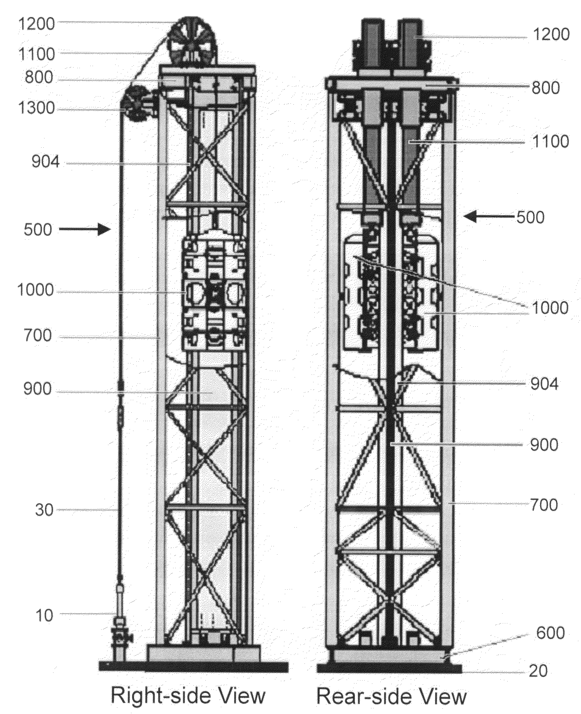
[0043]In accordance with one embodiment of the present invention, the linear motor actuated pumping unit 500 is placed adjacent to the wellhead 10 as illustrated in FIG. 5. The front-side of the pumping unit 500 faces the wellhead 10. FIG. 5 presents a right-side view and a rear-side view of the pumping unit 500. The base skid 600 of the pumping unit 500 is mounted on top of a concrete foundation 20. A vertical steel structure 700 is constructed on top of the base skid 600 to support the weight of the functional components in the pumping unit 500. An upper plate 800 is attached to the top of the vertical steel structure 700. A two-sided stator track 900 is housed in the interior of the vertical steel structure 700. The bottom end of the stator track 900 is attached to the base skid 600, while the top end is attached to the upper plate 800. T...


PUM


Abstract

A compact well pumping unit actuated by a linear motor with one or more counterweights directly attached to the slider. In one embodiment, two slider units are joined to form a rectangular complex around a two-sided stator track mounted vertically inside of a vertical steel frame. A belt assembly connects the slider complex to the polished rod of the well pump. The belt assembly passes over a first set of pulley wheels mounted on top of the vertical steel frame and a second set mounted on the side of the vertical steel frame. Thus when the slider complex caused to moves up and down, the polished rod of the well pump is actuated by the linear motor.

Description

CROSS-REFERENCE TO RELATED APPLICATIONS[0001]This application claims the benefit of provisional application Ser. No. 60 / 857,622, filed Nov. 8, 2006, the contents of such application being hereby incorporated by reference.STATEMENT REGARDING FEDERALLY SPONSORED RESEARCH OR DEVELOPMENT[0002]Not applicable.THE NAMES OF THE PARTIES TO A JOINT RESEARCH AGREEMENT[0003]Not applicable.INCORPORATION BY REFERENCE OF MATERIAL SUBMITTED ON A COMPACT DISC[0004]Not applicableBACKGROUND OF THE INVENTION[0005]1. Field of the Invention[0006]This invention generally relates to a new apparatus for actuating a sucker rod pump on an oil well.[0007]2. Background Art[0008]For oil production, sucker rod pumps are typically installed in oil wells to extract the oil below which do not have enough pressure to rise to the surface. Oil is extracted by reciprocating the up and down motion of the sucker rod. Different means have been employed to actuate the sucker rod. The most popular prior art apparatus utilize...

Claims


Application Information

Patent Timeline
IPC IPC(8): E21B4/04
CPCE21B43/126
Inventor ZHANG, SHICHANG
Owner WUHAN JIANGHAN GASOLINEEUM MACHINERY
Why Eureka
Try Eureka