Partition mount with integrated plunger assembly

a technology of integrated plunger and partition mount, which is applied in the direction of curtain suspension devices, door/window protective devices, applications, etc., can solve the problems of jacks being considered by some to be relatively bulky, jacks being considered by some to be top-heavy at times,

Active Publication Date: 2010-02-09
ZIPWALL
View PDF151 Cites 51 Cited by
  • Summary
  • Abstract
  • Description
  • Claims
  • Application Information

AI Technical Summary

Benefits of technology

[0007]In this manner, by integrating the plunger within the pole, the present invention provides a system that is less top-heavy and therefore easier to use and install. Fewer components are needed, and a sleeker, light-weight, design is achieved, improving packaging and shipping efficiency. Assuming that the pole in which the anchor is mounted is part of a telescoping pole system, the anchor and plunger do not interfere with full travel of the interior pole with respect to other poles in the telescoping system. In this manner, operation of the telescoping pole system is not inhibited by the integrated plunger assembly.
[0009]In one embodiment, a mounting head is connected to a distal end of the plunger at a universal joint. The head is adapted for mating with a corresponding clip for securing a curtain to the plunger assembly. Compression of the spring operating on the plunger urges the head and clip against the ceiling. A retaining device, for example a tether in the form of a rope, chain, fastener, wire, cord, strap or plastic attachment, is used to connect the clip to the head. In one embodiment, the retaining device is detachable from the head, the clip, or both, so as not to limit positioning of the curtain between the head and the clip, such as in the case where a central portion of the curtain is to be supported by the plunger assembly. The retaining device can be fixed to the head and clip by fasteners, for example by hooks, clamps, clips or clasps. In one embodiment, the head and / or clip includes a keyed tether slot and the tether includes a key or extension that mates with the tether slot, such that the retaining device can be removably secured to the clip and / or head.
[0012]In another embodiment, the pole comprises an extension pole having multiple telescoping segments, and the head end of the pole is at an inner segment of the extension pole. In another embodiment, the extension pole further comprises a locking mechanism that secures the positioning of adjacent pole segments relative to each other. In another embodiment, the anchor is secured within the pole so as not to inhibit sliding action of the inner segment of the pole relative to other segments of the pole.
[0020]In another embodiment, the partition mount further comprises a dampener for dampening force imparted on the anchor by rapid release of the mounting head under bias by the compression mechanism.
[0021]In another aspect, the present invention is directed to a partition mount. An elongated adjustable-length extension pole includes multiple telescoping segments, the pole having a foot end and a head end, the head end of the pole being at an inner segment of the pole, and the pole having a longitudinal axis. An anchor is secured within the pole at a position proximal to the head end. A mounting head extends from the head end of the pole, and travels in a direction along the longitudinal axis of the pole relative to the anchor position. The mounting head includes a neck that extends into the head end of the pole and a mounting unit that removably secures a sheet of material, the neck and mounting unit being coupled by a pivot joint that permits pivot of the mounting unit relative to the pole. A compression mechanism comprising a spring biases the position of the head in an outward direction away from the anchor. A retainer prevents the mounting head from being released from the head end of the pole by controlling a travel distance of the mounting head.

Problems solved by technology

Some simply nail, screw, or staple a curtain or partition material to the floor, ceiling, and abutting walls, resulting in damage to their surfaces.
While this system is durable, easy-to-use, and reliable, the jack could be considered by some to be top-heavy at times, especially when mounted to a relatively long pole.
In addition, the jack could be considered by some to be relatively bulky during shipping and distribution.

Method used


Image

  • Partition mount with integrated plunger assembly
  • Partition mount with integrated plunger assembly
  • Partition mount with integrated plunger assembly

Examples


Embodiment Construction

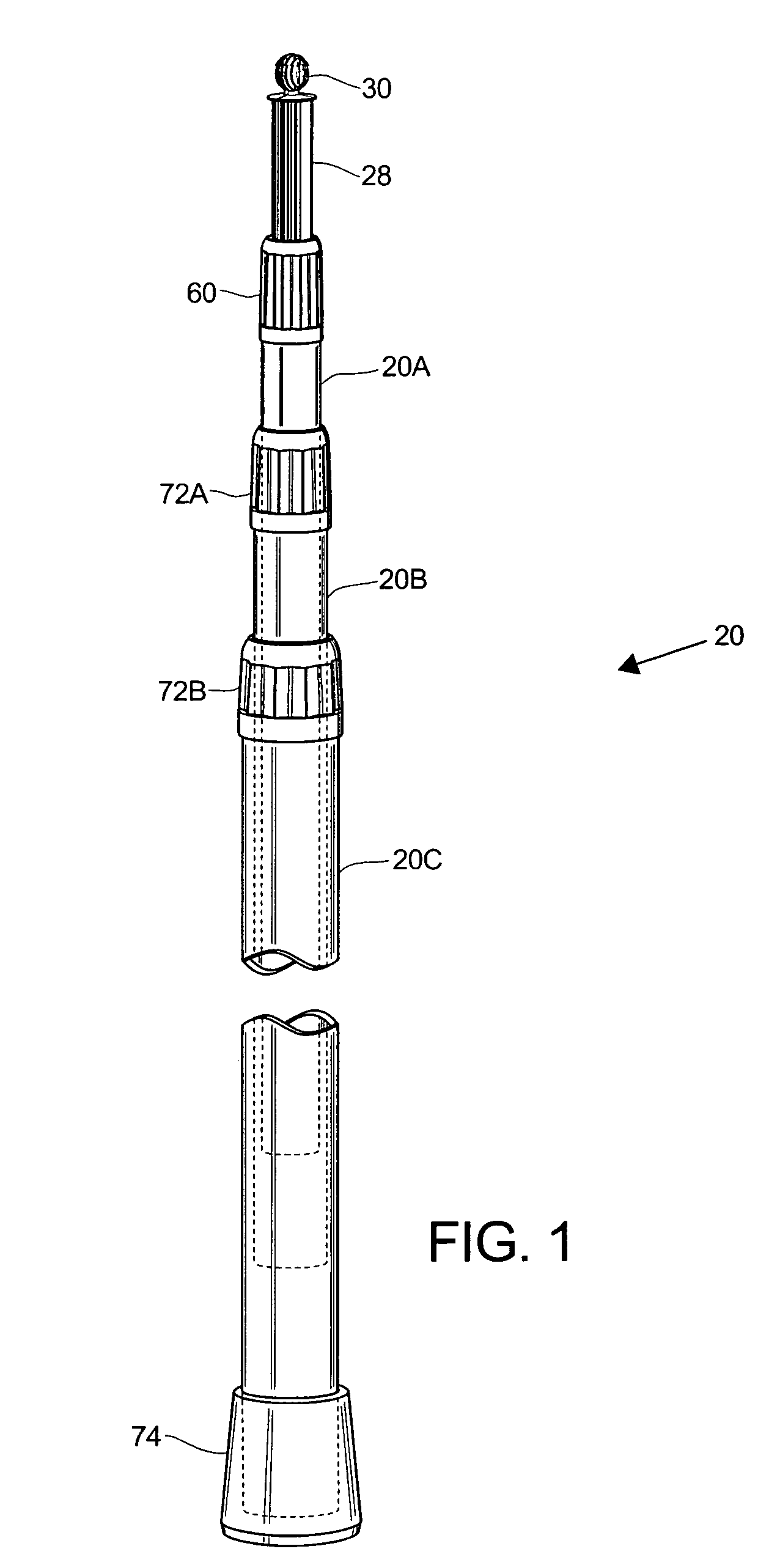
[0038]FIG. 1 is a side view of a telescoping extension pole curtain mounting system including an integrated plunger assembly in accordance with the present invention. The pole 20 includes an inner pole 20A, an intermediate pole 20B, and an outer pole 20C that extend with respect to each other in telescopic fashion. The relative extensions of the inner, intermediate, and outer poles 20A, 20B, 20C are typically set by rotating the poles with respect to each other, and, as a result of the rotation, an interior locking mechanism fixes their respective lengths. External collars 72A, 72B prevent pinching of fingers or other objects between the respective poles and optionally can provide an external locking mechanism for locking the respective longitudinal positions of the poles. A foot 74 formed of high-friction material such as rubber, at the bottom of the outer pole 20C, prevents the pole from slipping in a lateral direction when mounted on a surface, such as a floor.

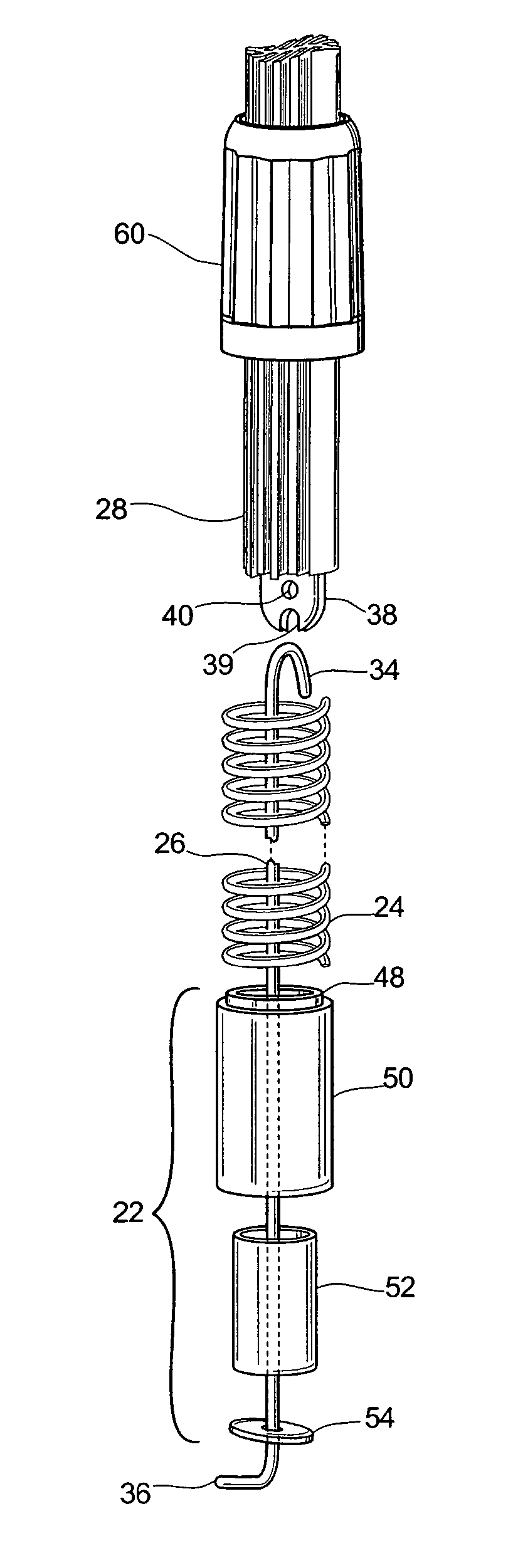
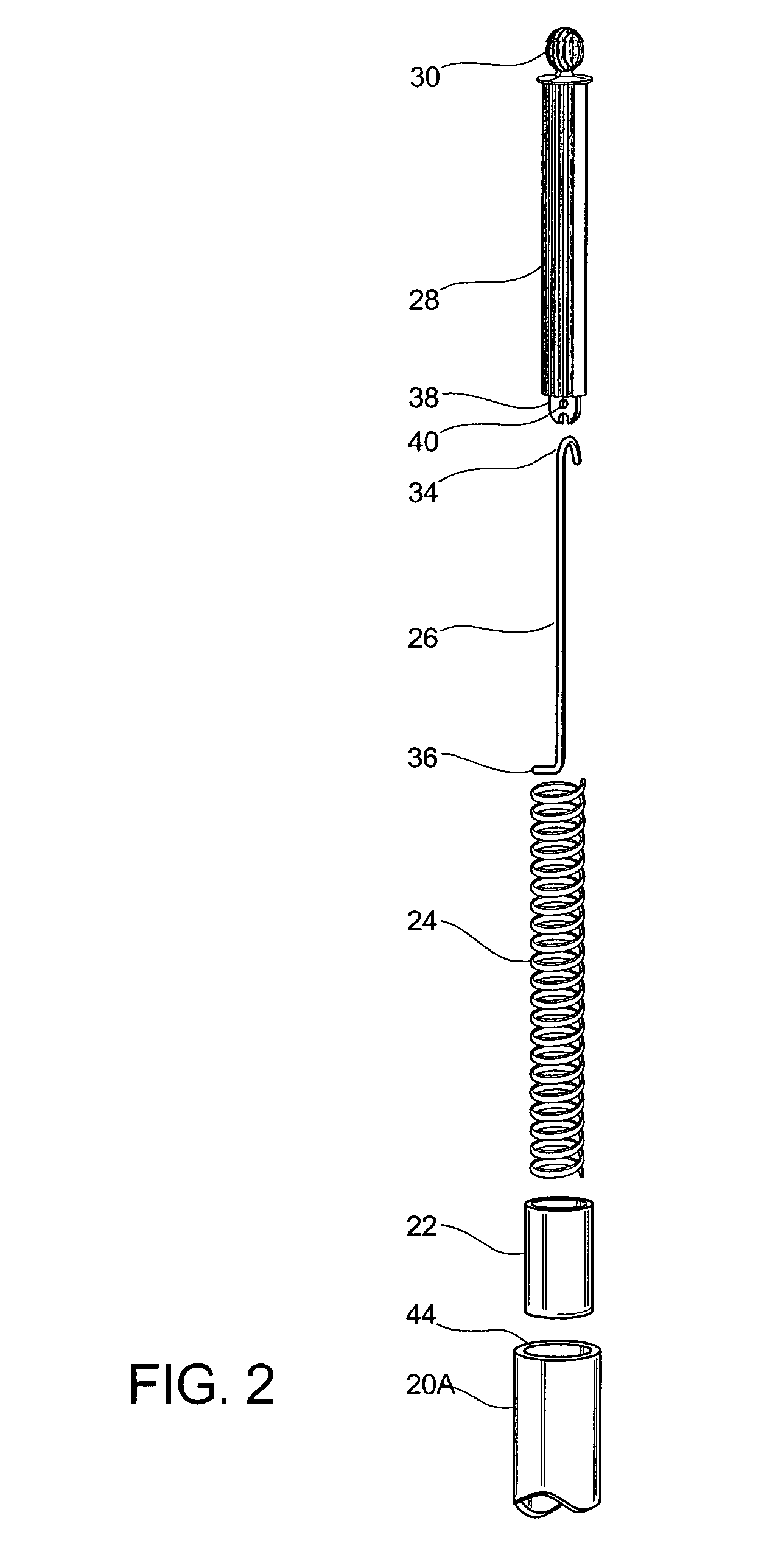
[0039]A plunger 28,...


PUM


Abstract

A partition mount system includes an integrated plunger assembly. The integrated plunger assembly is constructed and arranged to be integrated into an interior of an end of an extension pole, for example a standard telescoping extension pole. Mounting of the plunger in an interior portion of the pole in this manner provides for a sleek design that is relatively lightweight. Assuming that the pole in which the anchor is mounted is part of a telescoping pole system, the anchor and plunger do not interfere with full travel of the interior pole with respect to other poles in the telescoping system. In this manner, operation of the telescoping pole system is not inhibited by the integrated plunger assembly.

Description

RELATED APPLICATIONS[0001]This application claims the benefit of U.S. Provisional Application Ser. No. 60 / 569,534, filed May 10, 2004, and U.S. Provisional Application Ser. No. 60 / 598,782, filed Aug. 3, 2004, the contents of each being incorporated herein by reference, in their entirety.BACKGROUND OF THE INVENTION[0002]Partition systems are employed to isolate portions of a building or room, by serving as a barrier to dust, noise, light, odors, and the like. In construction zones, partitions are useful for protecting a clean area from a work area, for example, protecting an area where furniture and rugs are temporarily stored from an area where wood floors are being refinished.[0003]Workers at construction sites often use rudimentary techniques for installing partitions. Some simply nail, screw, or staple a curtain or partition material to the floor, ceiling, and abutting walls, resulting in damage to their surfaces. Others tape, or otherwise adhere, a curtain or plastic sheet to th...

Claims


Application Information

Patent Timeline
Patent Type & Authority Patents(United States)
IPC IPC(8): A47H13/00A47G5/00E04G21/24E04G21/30
CPCE04G21/24E04G21/30E04H12/182E04G21/26A47H1/022A47H13/00E04G21/243E04G25/08E04G2025/006
Inventor WHITTEMORE, JEFFREY P.
Owner ZIPWALL
Why Eureka
Try Eureka