Photographing apparatus

a technology of photographing and apparatus, applied in the field of photographing apparatus, can solve the problems of many images being corrected in a long time and troublesome manual tilt correction, and achieve the effect of high quality stereographic image, simple acquisition, and high quality

Active Publication Date: 2008-06-05
FUJIFILM CORP
View PDF1 Cites 234 Cited by
  • Summary
  • Abstract
  • Description
  • Claims
  • Application Information

AI Technical Summary

Benefits of technology

[0031]According to the twelfth aspect of the present invention, when a stereographic image is photographed by two or more photographic optical systems with their setting positions and shooting directions adjustable, an attitude of the apparatus body and a setting position and a shooting direction of each of the photographic optical systems are detected while the photographing apparatus is photographing a subject. The photographed image is recorded on a recording medium with the information on the detected attitude of the apparatus body, information on physical relationship

Problems solved by technology

That manual tilt correction is very troublesome, however.
It

Method used


Image

  • Photographing apparatus
  • Photographing apparatus
  • Photographing apparatus

Examples


first embodiment

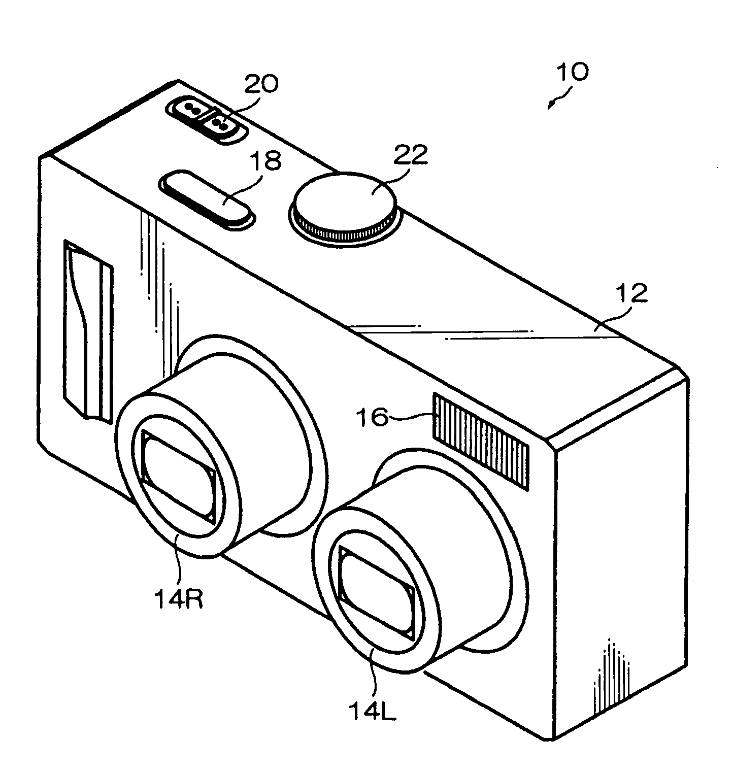
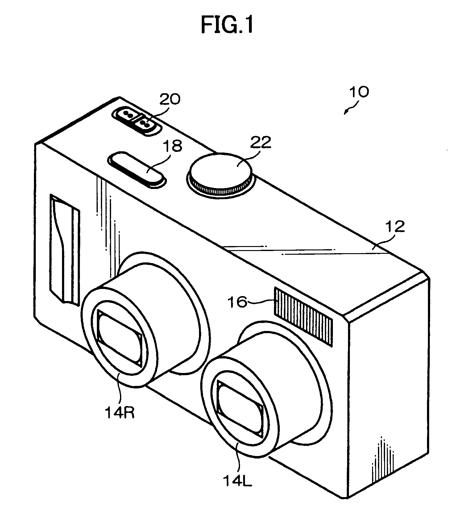
[0050]FIGS. 1 and 2 are a front perspective view and a back perspective view of an appearance of a digital camera which employs the present invention.

[0051]The digital camera 10 is adapted to photograph the same subject from two viewpoints on the left and right of the subject at the same time to produce a three-dimensional (3D) image of the subject.

[0052]The camera body (apparatus body) 12 of the digital camera 10 has a form of rectangular box with a pair of photographing lenses 14R, 14L, a flash 16 and the like provided on the front side, and a shutter button 18, a power / mode switch 20, a mode dial 22 and the like provided on the top as shown in FIG. 1.

[0053]The camera body 12 has a monitor 24, a zoom button 26, a directional button 28, a MENU / OK button 30, a DISP button 32, a BACK button 34, a macro button 36 and the like provided on the back as shown in FIG. 2.

[0054]The camera body 12 has a tripod socket, a battery cover to open and close, and the like on the bottom, though they ...

second embodiment

[0219]FIG. 14 is a plan view showing a configuration of a substantial part of the digital camera to which the present invention is applied.

[0220]As shown in FIG. 14, the digital camera of the embodiment is adapted to have the photographing lenses 14R and 14L horizontally movable and their setting positions adjustable. Specifically, the digital camera is adapted to adjust the base line length D (with the shooting directions fixed).

[0221]As the digital camera of second embodiment is the same as that of the first embodiment except that the digital camera of the second embodiment can adjust the base line length D, only the mechanism for adjusting the base line length will be described here.

[0222]As shown in FIG. 14, the photographing lenses 14R and 14L have the image pickup devices 134R and 134L attached to the rear anchor parts of the lens tubes 15R and15L of the lenses. The image pickup devices 134R and 134L are arranged on the optical axes LR and LL of the photographing lenses 14R an...

third embodiment

[0232]FIG. 15 is a plan view showing a configuration of a substantial part of the digital camera to which the present invention is applied.

[0233]As shown in FIG. 15, the digital camera of the embodiment is adapted to have the photographing lenses 14R and 14L turn so that the shooting direction (the orientation of the optical axes LR and LL), i.e., a convergence angle (an angle formed by the optical axes LR and LL of the photographing lenses 14R and 14L) γ can be adjusted (with the setting position fixed).

[0234]As the digital camera of the third embodiment is the same as that of the first embodiment except that the digital camera of the third embodiment can adjust the convergence angle, only the mechanism for adjusting the convergence angle will be described here.

[0235]As shown in FIG. 15, the photographing lenses 14R and 14L have the image pickup devices 134R and 134L attached to the rear anchor parts of the lens tubes 15R and 15L of the lenses. The image pickup devices 134R and 134...


PUM


Abstract

Photographing apparatus having a plurality of photographic optical systems, comprises: an attitude detecting device which detects an attitude of the apparatus body; a physical relationship information obtaining device which obtains information on physical relationship among the photographic optical systems setting; and a shooting direction information obtaining device which obtains information on the shooting direction of each of the photographic optical systems. The images photographed by each of the photographic optical systems may be corrected based on information on the attitude of the apparatus body, information on the physical relationship among the photographic optical systems, and information on the shooting direction of each of the photographic optical systems. Thereby it enables to easily correct tilt and the like of the images.

Description

BACKGROUND OF THE INVENTION[0001]1. Field of the Invention[0002]The present invention relates to photographing apparatus, specifically to photographing apparatus for photographing a stereographic image.[0003]2. Description of the Related Art[0004]Generally, a stereographic image is photographed in such a manner as the same subject is photographed from two or more viewpoints at the same time. For that purpose, a camera for photographing a stereographic image (hereinafter referred to as a three-dimensional (3D) camera) is provided with two or more photographing devices (for example, see Japanese Patent Application Laid-Open No. H6-105339, No. H8-111874, and No. H1-341522).[0005]When a photographer takes a stereographic image with the 3D camera, the photographer needs to photograph a subject so that the image is taken along a line that matches the eye level of a viewer of the photographed image. Specifically, when a photographer is to photograph a stereographic image with two photograp...

Claims


Application Information

Patent Timeline
IPC IPC(8): G03B17/00
CPCG03B17/00
Inventor UENO, TOSHIHARU
Owner FUJIFILM CORP
Why Eureka
Try Eureka