System and method for securing implants to soft tissue

a soft tissue and implant technology, applied in the field of system and method for securing implants to soft tissue, can solve the problems of difficult for surgeons to accurately deploy the insertion device, substantial difficulty in removing and adjusting such devices, and the difficulty of fixing devices, etc., to achieve convenient and convenient use, simple structure, and convenient use

Inactive Publication Date: 2008-07-10
SPRINGBOARD MEDICAL VENTURES
View PDF43 Cites 17 Cited by
  • Summary
  • Abstract
  • Description
  • Claims
  • Application Information

AI Technical Summary

Benefits of technology

[0013]Such embodiment further advantageously allows for post-operative adjustment whereby the suture with piton members attached thereto can be selectively pulled along the desired pathway to the extent necessary to adjust the suture position and / or introduce a greater degree of tension thereto. Along these lines, such embodiment has the additional advantage of being completely removable from the patient's body by virtue of its ability to selectively move through and out of tissue.
[0034]It is additionally an object of the present invention to provide a novel surgical procedure for the formation and affixation of a suburethral sling whereby the opposed ends of the sling are secured near or at the posterior side of the pubic bone in the retropubic space with the opposed ends of the sling being secured to either the periosteum, Cooper's ligament, fascia or the pubic bone itself.

Problems solved by technology

Although such prior art anchor devices generally provide sufficient support to the various sutures and grafts affixed thereto, such fixation devices suffer from numerous drawbacks.
In this regard, it is difficult for the surgeon to accurately deploy the insertion device such that the anchor is correctly inserted at the target site.
Moreover, substantial difficulty arises in removing and adjusting such devices.
This latter task is especially problematic with respect to bone-screw devices insofar as the surgeon attempting to remove the same must take great care to insure that the removal device, also typically comprising a battery-powered screw driver, properly unscrews the anchor member from its seated position.
Other prior art anchor devices are even further problematic insofar as the same are often irretrievable once deployed, especially in situations where the same are deployed too deeply into the bone mass.
Additional problems exist with prior art bone fixation systems insofar as the same have a tendency to become dislodged over time from their seated position.
In this regard, due to the repetitive application of stress or strain upon the bone anchor via the suture or soft tissue attached thereto, such anchors can eventually become loose and slip out of engagement from their fixed position.
Moreover, even to the extent such bone anchoring systems remain securely in position, recent research tends to indicate that such bone fixation devices have a tendency to actually cut the sutures sought to be held thereby.
Separate and apart from the drawbacks associated with the use of prior art bone anchoring systems is the fact that often times anchor systems provide far more structural support than is necessary for a given surgical application.
While such slings typically require little to no tension once fixed into position, due to the lack of alternative means for affixing the opposed ends of such sling into position relative to the pubic bone, such prior art bone anchor devices must necessarily be deployed.
Along these lines, a substantial risk exists simply by utilizing a retropubic route to gain access to the surgical site where such sling is affixed into position.
In this regard, accessing such surgical site via a retropubic route can increase the risk of bleeding and / or intestinal injury due to the proximity of blood vessels existing within and above the pubocervical fascia and the intestines.

Method used


Image

  • System and method for securing implants to soft tissue
  • System and method for securing implants to soft tissue
  • System and method for securing implants to soft tissue

Examples


Embodiment Construction

[0069]The detailed description as set forth below in connection with the appended drawings is intended as a description of the presently preferred embodiments of the invention, and is not intended to represent the only form in which the present invention may be constructed or utilized. The description sets forth the functions and sequences of steps for constructing and operating the invention in connection with the illustrated embodiments. It is understood, however, that the same or equivalent functions and sequences may be accomplished by different embodiments and that they are also intended to be encompassed within the scope of this invention.

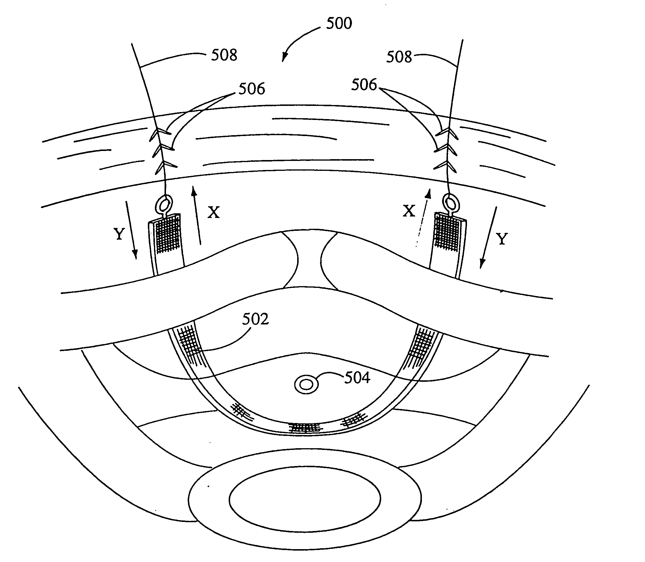
[0070]Referring now to the drawings, and particularly FIGS. 6-15. there are shown various embodiments of the devices and systems of the present invention for securing sutures, grafts, tissues and synthetic materials, and the like to bone, periosteum and other soft tissue. As is well known in the practice of medicine, a wide variety of surgica...


PUM


Abstract

Self-anchoring slings and deployment mechanisms for use therewith in selectively positioning a sling into position within the body. According to a preferred embodiment, a system is provided for securing a sling into fixed position within a target site of soft tissue within the body. The system includes an implantable sling having an elongate segment of material with an anchor mechanism formed on the ends thereof. The system also includes a non-mechanically assisted deployment mechanism for positioning the anchor mechanisms within the target site. The deployment mechanism has a manually operable handle having a deployment member extending distally therefrom, the deployment member being detachably fastenable to a respective one of said anchor mechanisms of said implantable sling. The deployment member is configured to guide the anchor mechanism through the soft tissue to the target site, and insert said anchor mechanism into said tissue at said target site.

Description

CROSS-REFERENCE TO RELATED APPLICATIONS[0001]The following patent application is a continuation of U.S. patent application Ser. No. 10 / 465,330 entitled SYSTEMS FOR SECURING SUTURES, GRAFTS & SOFT TISSUE TO BONE & PERIOSTEUM, which is a continuation-in-part of U.S. patent application Ser. No. 09 / 733,455 entitled SYSTEM AND METHOD FOR SECURING SUTURES TO BONE AND TISSUE, filed Dec. 8, 2000, which is a continuation-in-part of U.S. patent application Ser. No. 09 / 197,938 entitled SYSTEMS FOR SECURING SUTURES, GRAFTS AND SOFT TISSUE TO BONE AND PERIOSTEUM, now issued as U.S. Pat. No. 6,200,330, and further relies upon Disclosure Document No. 463,908 entitled Transvaginal Rectus-Fascia Anchor, filed Oct. 21, 1999; Disclosure Document No. 479243 entitled Adjustable Soft Tissue Attachment Device and System, filed Sep. 5, 2000; Disclosure Document entitled Transvaginal Rectus-Fascia Attachment, filed Mar. 1, 2000, disclosure document number not assigned; Disclosure Document entitled Transvagi...

Claims


Application Information

Patent Timeline
Patent Type & Authority Applications(United States)
IPC IPC(8): A61F2/00A61B17/04A61B17/064A61F2/08
CPCA61B17/0401A61B17/0642A61B2017/0412A61B2017/0414A61B2017/0427A61B2017/0438A61F2002/0888A61B2017/0445A61B2017/0454A61B2017/0461A61B2017/0462A61F2/0811A61F2002/0858A61B2017/044
Inventor BENDEREV, THEODORE V.
Owner SPRINGBOARD MEDICAL VENTURES
Why Eureka
Try Eureka