Method of Treating Vaginal Prolapse

a vaginal prolapse and treatment method technology, applied in the direction of prosthesis, surgical staples, ligaments, etc., can solve the problems of difficult for surgeons the fixation device suffers from numerous drawbacks, and the surgeon is difficult to accurately deploy the insertion device, etc., to achieve the effect of reducing the difficulty of removing and adjusting such devices

Inactive Publication Date: 2011-12-22
SPRINGBOARD MEDICAL VENTURES
View PDF2 Cites 4 Cited by
  • Summary
  • Abstract
  • Description
  • Claims
  • Application Information

AI Technical Summary

Benefits of technology

Such embodiment further advantageously allows for post-operative adjustment whereby the suture with piton members attached thereto can be selectively pulled along the desired pathway to the extent necessary to adjust the suture position and / or introduce a greater degree of tension thereto. Along these lines, such embodiment has the additional advantage of being completely removable from the patient's body by virtue of its ability to selectively move through and out of tissue.
Another object of the present invention is to provide a self-anchoring sling that enables the sling to be securely affixed into position within a site of soft tissue such that the same resists sag or otherwise lessens its ability to provide support that can further preferably be deployed via a trans-obturator route, and preferably via a system and method that enables the same to be deployed via a single access route, such as a single vaginal incision, to thus eliminate risks associated with sling delivery via a retro-pubic route.

Problems solved by technology

Although such prior art anchor devices generally provide sufficient support to the various sutures and grafts affixed thereto, such fixation devices suffer from numerous drawbacks.
In this regard, it is difficult for the surgeon to accurately deploy the insertion device such that the anchor is correctly inserted at the target site.
Moreover, substantial difficulty arises in removing and adjusting such devices.
This latter task is especially problematic with respect to bone-screw devices insofar as the surgeon attempting to remove the same must take great care to insure that the removal device, also typically comprising a battery-powered screwdriver, properly unscrews the anchor member from its seated position.
Other prior art anchor devices are even further problematic insofar as the same are often irretrievable once deployed, especially in situations where the same are deployed too deeply into the bone mass.
Additional problems exist with prior art bone fixation systems insofar as the same have a tendency to become dislodged over time from their seated position.
In this regard, due to the repetitive application of stress or strain upon the bone anchor via the suture or soft tissue attached thereto, such anchors can eventually become loose and slip out of engagement from their fixed position.
In this regard, many fixation techniques are susceptible to failure with misplacement or pull-out of anchors and eventual dislodgement of the structure / graft supported thereby with coughing, vomiting or other violent activity.
Moreover, even to the extent such bone anchoring systems remain securely in position, recent study tends to indicate that such bone fixation devices may actually have a tendency to cut the sutures sought to be held thereby.
Separate and apart from the drawbacks associated with the use of prior art bone anchoring systems is the fact that often times anchor systems provide far more structural support than is necessary for a given surgical application.
While such slings typically require little to no tension once fixed into position, due to the lack of alternative means for affixing the opposed ends of such sling into position relative to the pubic bone, such prior art bone anchor devices must necessarily be deployed.
Along these lines, a substantial risk exists simply by utilizing a retropubic route to gain access to the surgical site where such sling is affixed into position.
In this regard, accessing such surgical site via a retropubic route can increase the risk of bleeding and / or intestinal injury due to the proximity of blood vessels existing within and above the pubocervical fascia and the intestines.

Method used


Image

  • Method of Treating Vaginal Prolapse
  • Method of Treating Vaginal Prolapse
  • Method of Treating Vaginal Prolapse

Examples


first embodiment

Referring now to FIG. 21, there is shown the use of the system 800 to deploy the implant 802 via the deployment mechanism 804. In the procedure illustrated, such implant 802 is being deployed through an incision 822 formed within the vaginal wall 820 to thus enable a urethra 824 to ultimately become supported thereby. To that end, it is contemplated that such deployment may take one of two forms. the anchor mechanisms 808 housed within the deployment mechanism are compressed to assume a first deployment configuration and, once released therefrom, assume an expanded configuration that enables the same to remain fixed in position. Alternatively, the anchor mechanisms may simply assume a single state and deploy directly into tissue at a desired surgical site. As will be appreciated, however, other techniques will be readily apparent to those skilled in the art for use in deploying the anchor mechanisms of the present invention.

In this regard, the procedure depicted in FIG. 21 represen...

second embodiment

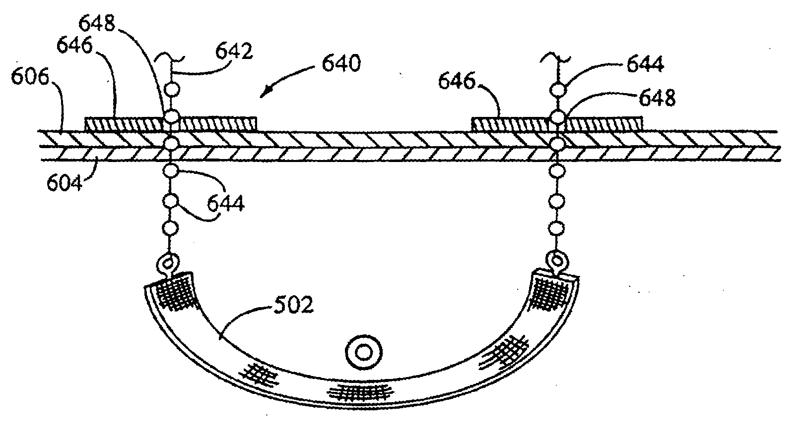
Referring now to FIGS. 32 and 32a, there is shown a percutaneously delivered support mechanism operative to impart urethral support for the treatment of incontinence. As illustrated, the implant 340 is comprised of an elongate backing or sling portion 342 having anchoring mechanisms or elements 344 formed on the respective ends thereof. As per the embodiment discussed with respect to FIGS. 27-31, the implant 340 is positioned within the vagina and underneath the urethra extending thereabove. The anchoring elements 344 are thus percutaneously compressed into the vagina which causes the implant 340, and more importantly the support portion 342 thereof to remain secured into position and provide support to the urethra 312. With respect to such anchoring mechanisms 344, the same may take any of those anchoring mechanisms disclosed herein suitable for such procedure, and in particular those disclosed in FIGS. 9 and 10. As will be readily appreciated by those skilled in the art, the impla...

embodiment 700

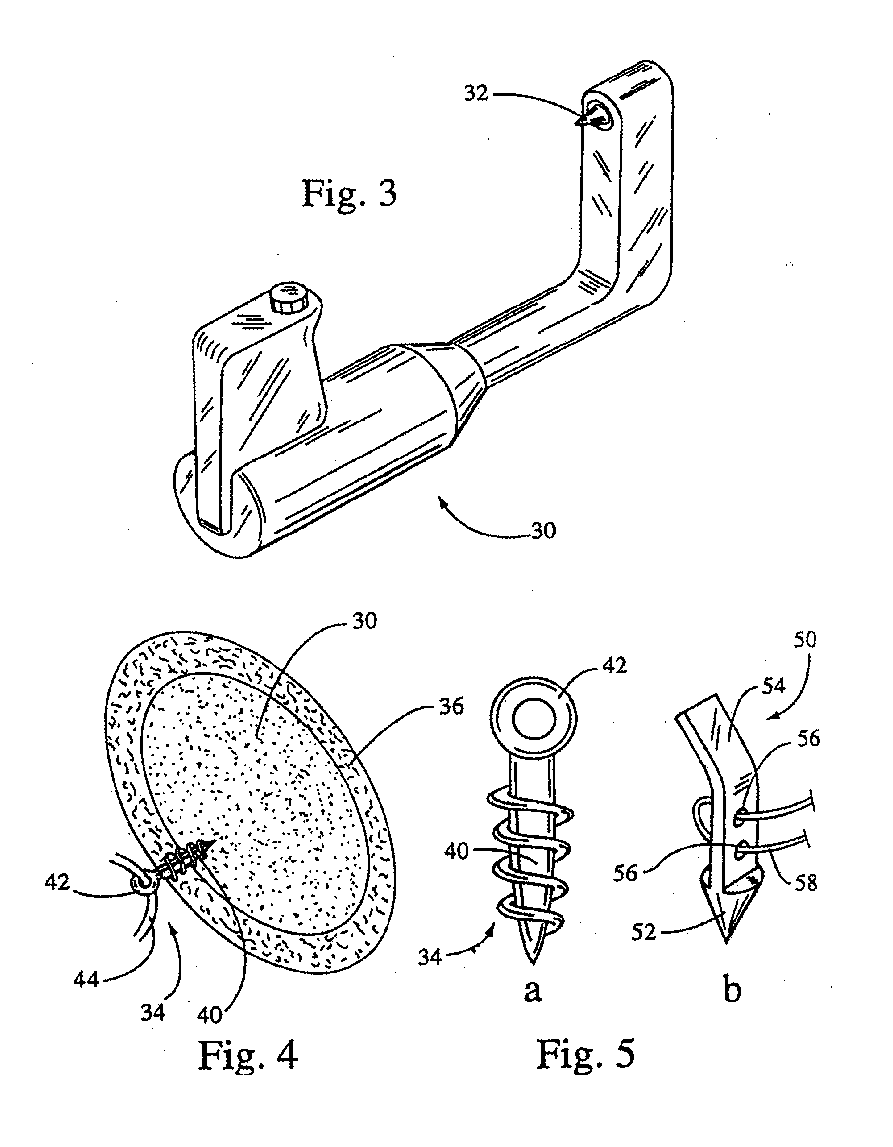
Referring now to FIGS. 19-19c, and initially to FIG. 19, there is shown an additional embodiment 700 of an anchoring system for securing a suture-like cord or line 508 at a desired location. As per the embodiments depicted in FIGS. 17 and 18, the embodiment shown includes an anchor plate 702 having at least one, and preferably two to four, channels 704 extending therethrough for receiving suture-like cords 508. As per the aforementioned embodiments, the anchor plate 702 may likewise be secured into position with a fastener mechanism or, alternatively, merely be positioned at a desired site upon fascia or soft tissue with the ultimate tension imparted thereto by the sutures 508 held thereby causing the same to remain resident at such site. As to the embodiment shown, the anchoring plate 702, once positioned, is operative to receive the suture line or lines 508 through the channels 704 defined thereby. As more clearly illustrated in the cross-sectional view of FIG. 19a, the suture-lik...


PUM

PropertyMeasurementUnit
areaaaaaaaaaaa
surface areaaaaaaaaaaa
compressaaaaaaaaaa

Abstract

A method of treating prolapsed vagina by tacking the prolapsed vagina to tissue proximate the obturator foramens with anchor mechanisms applied from inside the vagina.

Description

STATEMENT RE: FEDERALLY SPONSORED RESEARCH / DEVELOPMENTNot ApplicableBACKGROUND OF THE INVENTIONThe use of surgical suture anchors for use in attaching soft tissue to bone is well known in the art. In this regard, such anchoring mechanisms have found widespread applicability for a number of surgical procedures, and in particular orthopedic, gynecologic and urologic procedures. Exemplary of such devices include bone screws or anchors that are implantable within bone which further have formed thereon an eyelet or other type of assembly to which may be affixed suture lines or a segment of soft tissue. Exemplary of such devices include those devices disclosed in U.S. Pat. Nos. 5,370,662, and 5,443,482 to Stone, et al. and U.S. Pat. No. 4,738,255 to Gobel, et al.Generally, prior art anchor systems take one of two forms. The first configuration typically comprises a self-tapping bone screw, typically made of titanium, having an eyelet formed thereon to which the sutures or other material m...

Claims


Application Information

Patent Timeline
Patent Type & Authority Applications(United States)
IPC IPC(8): A61F2/04A61B17/04A61B17/064A61F2/00A61F2/08C23C14/08C23C14/22C23C14/28C23C14/50
CPCA61B17/0401A61F2002/0888A61B2017/0412A61B2017/0414A61B2017/0427A61B2017/0438A61B2017/044A61B2017/0454A61B2017/0461A61B2017/0462A61B2017/0464A61B2017/0647A61F2/0045A61F2/0811A61F2002/0858A61B17/0642
Inventor BENDEREV, THEODORE V.
Owner SPRINGBOARD MEDICAL VENTURES
Why Eureka
Try Eureka