This helps you quickly interpret patents by identifying the three key elements:
Problems solved by technology
Method used
Benefits of technology
Benefits of technology
[0016]The present invention was made in view of the foregoing problems, and an object of the present invention is to realize a transmission liquid crystal display device which can achieve further reduction of power consumption by reducing intensity of light absorbed not only by the liquid crystal panel but also by the color filter.
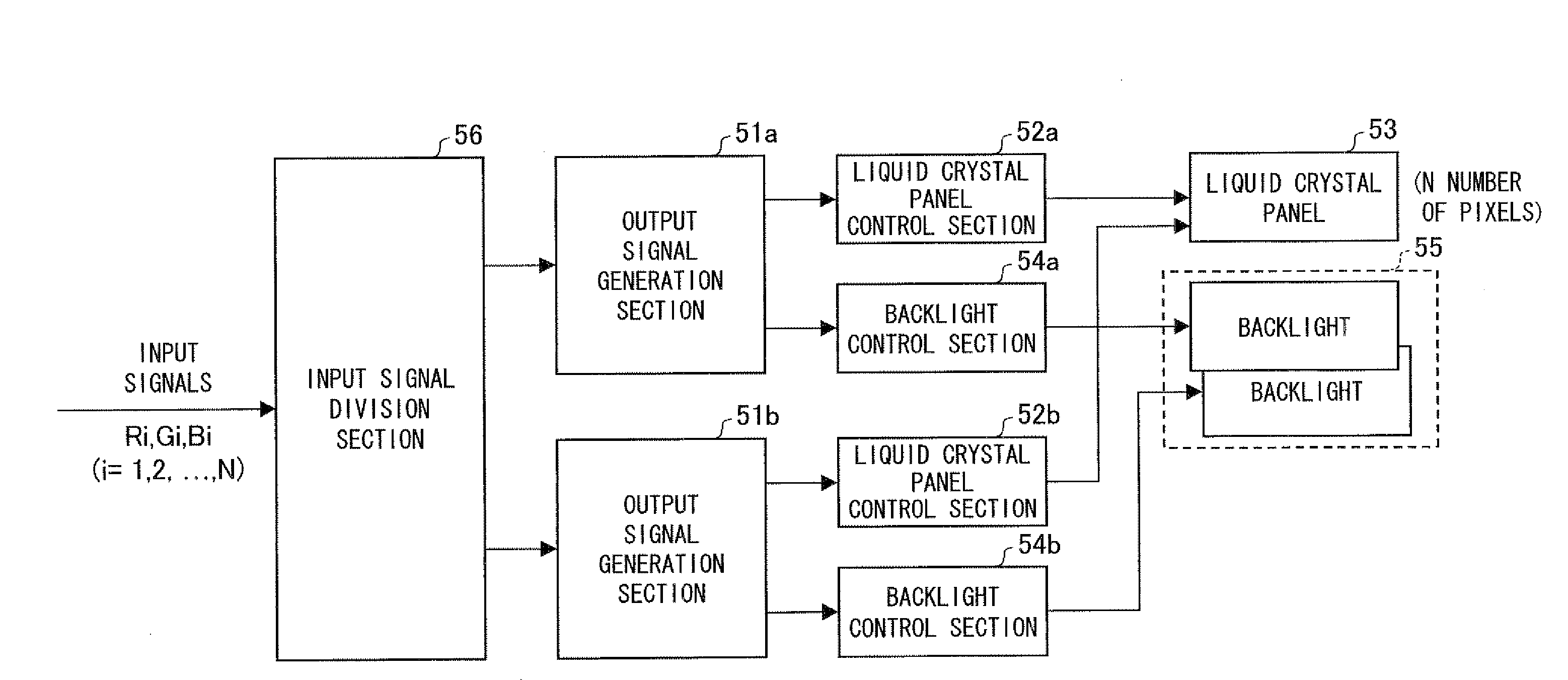
[0018]According to the arrangement, by using the liquid crystal panel in which a pixel is divided into four sud pixels as R, G, B, and W sub pixels, it is possible to partially incorporate R, G, and B components into the W sub pixel having no (or little) loss of light absorbed by the filter. As a result, it is possible to reduce light absorbed by the color filter, so that it is possible to realize reduction of power consumption of the transmission liquid crystal display device.
Problems solved by technology
Thus, in case where the liquid crystal panel is combined with a normal backlight which cannot control an emission luminance, it is impossible to reduce power consumption.
Method used
Image
Click on the blue label to locate the original text in one second.
Reading with bidirectional positioning of images and text.
Examples
embodiment 1
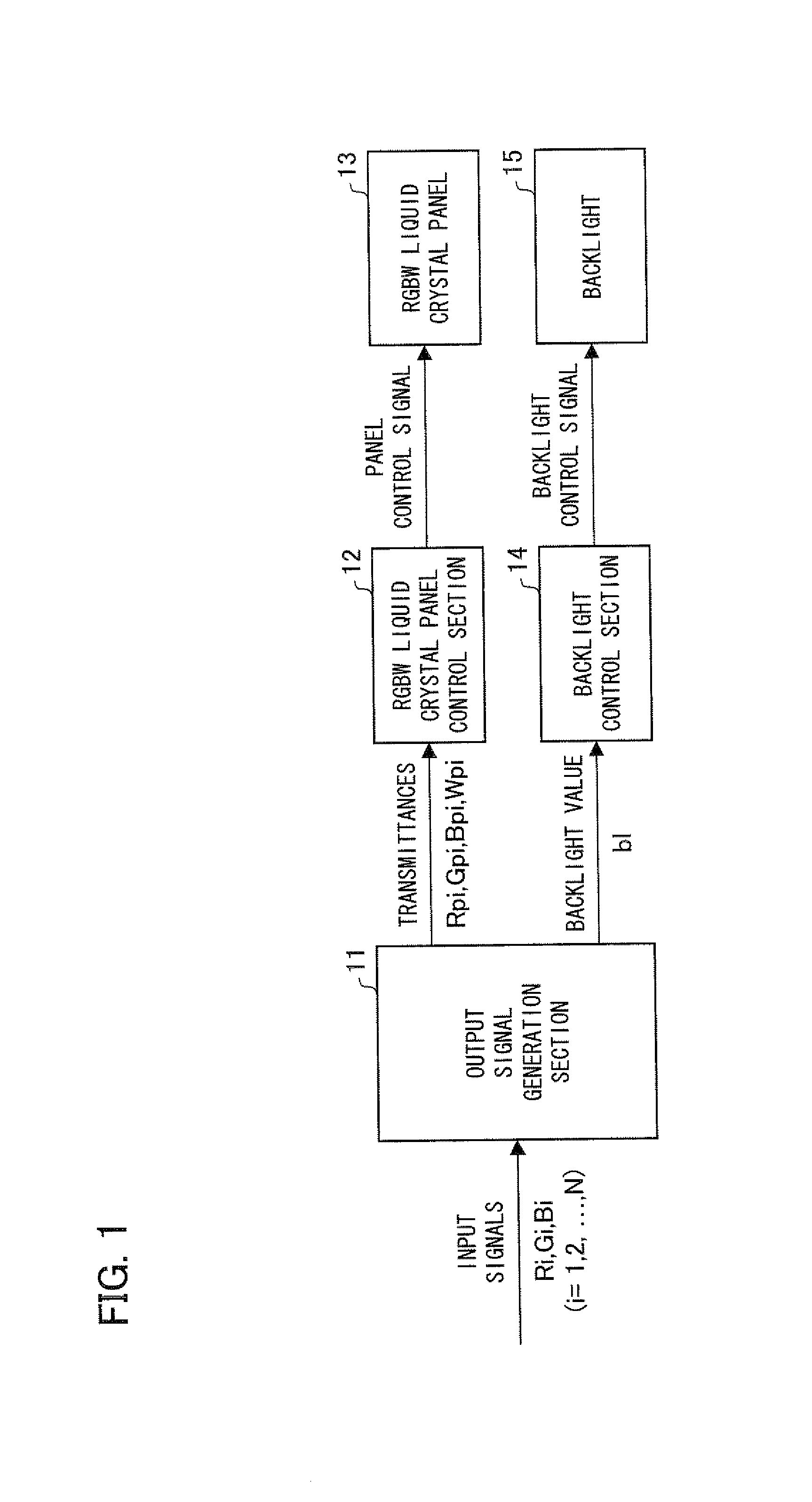
[0037]The following description will explain one embodiment of the present invention with reference to FIG. 1 to FIG. 10. First, with reference to FIG. 1, a schematic arrangement of a liquid crystal display device according to the present embodiment (hereinafter, referred to as the present liquid crystal display device) is described as follows.
[0038]The present liquid crystal display device includes an output signal generation section 11, an RGBW liquid crystal panel control section (hereinafter, referred to merely as a liquid crystal panel control section) 12, an RGBW liquid crystal panel (hereinafter, referred to merely as a liquid crystal panel) 13, a backlight control section 14, and a backlight 15.
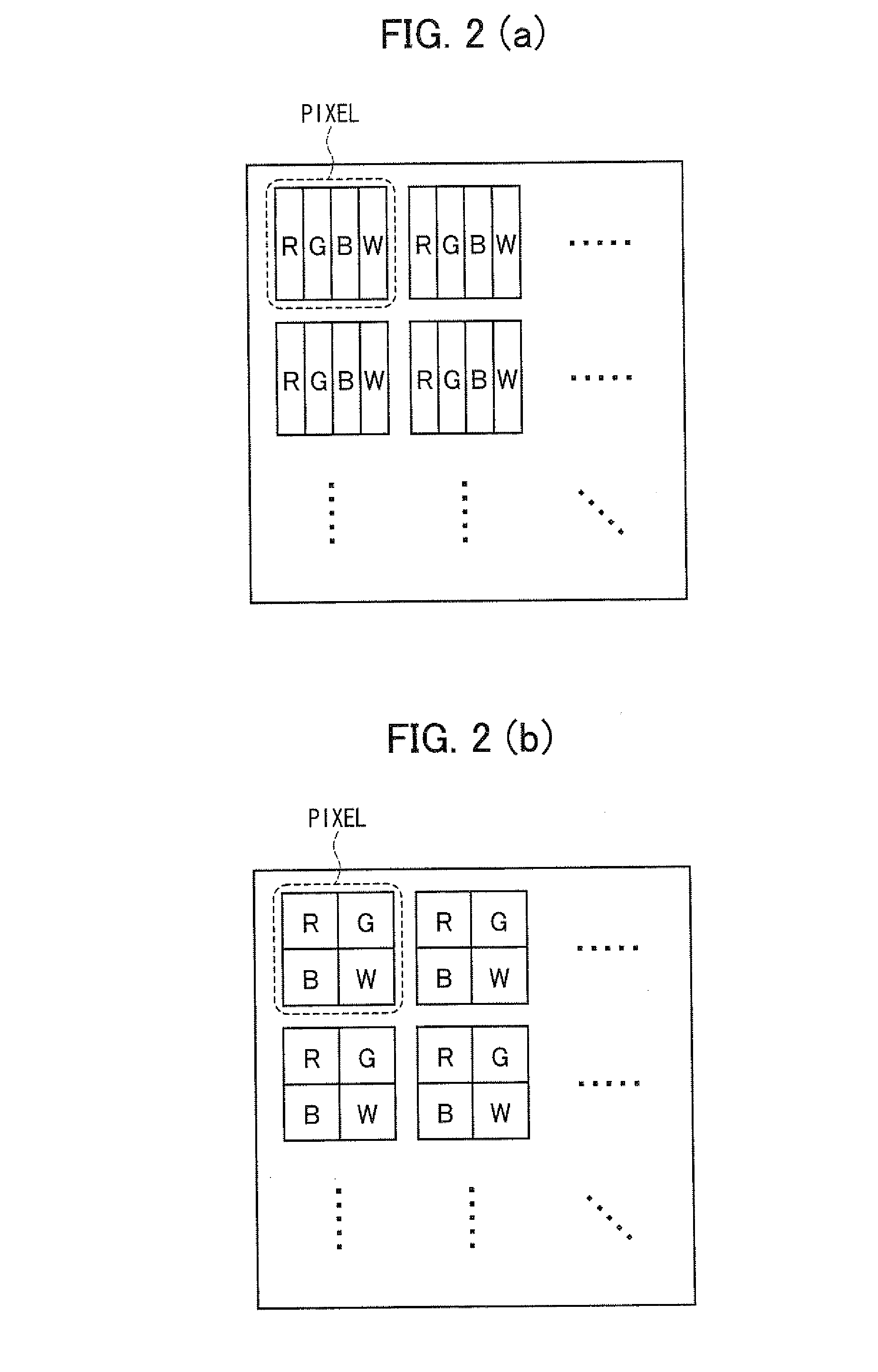
[0039]The liquid crystal panel 13 is arranged so that an N-number of pixels are disposed in a matrix manner, and each pixel is made up of four sub pixels as R (red), green (G), blue (B), and W (white) sub pixels as illustrated in FIG. 2(a) and FIG. 2(b). Note that, shapes and a positi...
embodiment 2
[0101]In Embodiment 1, the luminance Wi incorporated into the W sub pixel in the target pixel is max (Ri, Gi, Bi) / 2 in case where min (Ri, Gi, Bi)≧max (Ri, Gi, Bi) / 2. Further, in case where min (Ri, Gi, Bi)
Wi=min(max(Ri,Gi,Bi) / 2, min(Ri,Gi,Bi))
[0102]However, in Embodiment 1, the W sub pixel luminance Wi calculated by the foregoing expression is optimal strictly only in case where a white luminance property of the RGB sub pixels is equal to a white luminance property of the W sub pixel. Herein, the condition under which a white luminance property of the RGB sub pixels is equal to a white luminance property of the W sub pixel means a condition under which a display luminance P1 in case where a transmittance of each of the RGB sub pixels is x % and a transmittance of the W sub pixel is 0% is equal to a displa...
PUM
Abstract
The transmission liquid crystaldisplay device includes a liquid crystal panel and a backlight, wherein the liquid crystal panel has pixels each of which is divided into four sub pixels as red (R), green (G), blue (B), and white (W) sub pixels. Further, an emission luminance of the backlight can be controlled.
Description
[0001]This Nonprovisional application claims priority under 35 U.S.C. § 119(a) on Patent Application No. 300845 / 2006 filed in Japan on Nov. 6, 2006 and Patent Application No. 008457 / 2007 filed in Japan on Jan. 17, 2007, the entire contents of which are hereby incorporated by reference.FIELD OF THE INVENTION[0002]The present invention relates to a transmission liquid crystal display device using an active backlight as a light source.BACKGROUND OF THE INVENTION[0003]There are various kinds of color displays, and these color displays are in practical use. Flat type displays are roughly categorized into a self-luminous display such as a PDP (plasma display panel) and a non-luminous display represented by an LCD (liquid crystal display device). As the LCD which is the non-luminous display, a transmission LCD having a backlight disposed on a rear side of a liquid crystal panel is known.[0004]FIG. 11 is a cross sectional view illustrating a general structure of the transmission LCD. The tr...
Claims
Application Information
Patent Timeline
Application Date:The date an application was filed.
Publication Date:The date a patent or application was officially published.
First Publication Date:The earliest publication date of a patent with the same application number.
Issue Date:Publication date of the patent grant document.
PCT Entry Date:The Entry date of PCT National Phase.
Estimated Expiry Date:The statutory expiry date of a patent right according to the Patent Law, and it is the longest term of protection that the patent right can achieve without the termination of the patent right due to other reasons(Term extension factor has been taken into account ).
Invalid Date:Actual expiry date is based on effective date or publication date of legal transaction data of invalid patent.

