System and Method for Transparent Virtual Routing

Inactive Publication Date: 2008-09-04
GOOGLE TECH HLDG LLC
View PDF15 Cites 33 Cited by
  • Summary
  • Abstract
  • Description
  • Claims
  • Application Information

AI Technical Summary

Benefits of technology

[0021]The present invention relates to a system and method of transparent virtual routing designed to enable flexible deployment of IP networking within access networks, at minimal administrative, operational and capital costs. In an exemplary embodiment the inventive transparent virtual routing scheme allows a single large IP subnet to be assigned for

Problems solved by technology

Additionally, multicast IP packets being sent from one or more sources to multiple destinations may b

Method used


Image

  • System and Method for Transparent Virtual Routing
  • System and Method for Transparent Virtual Routing
  • System and Method for Transparent Virtual Routing

Examples


Embodiment Construction

Architectural and Operational Overview

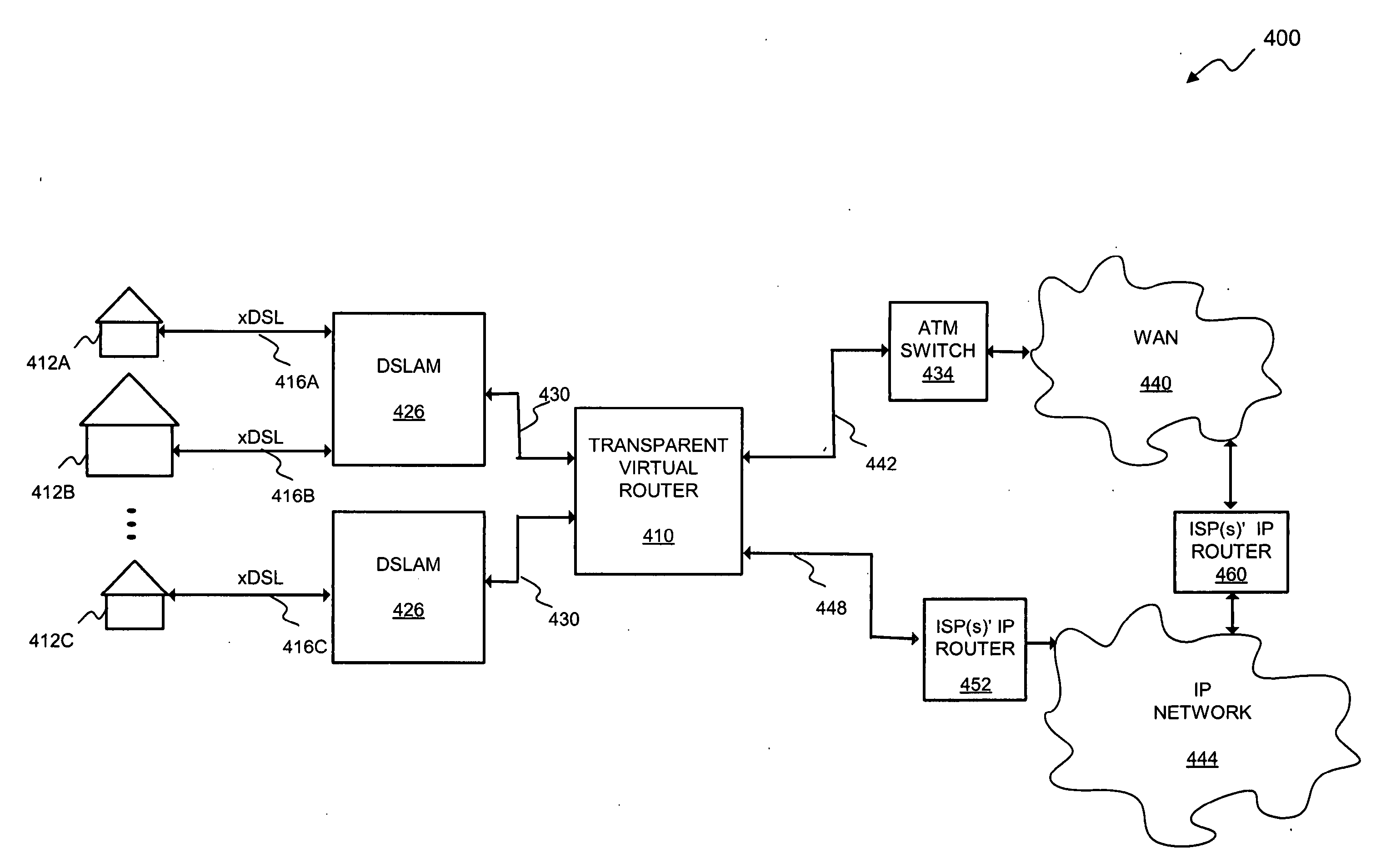
[0047]FIG. 4 is a block diagram of a telecommunications system 400 incorporating a transparent virtual router 410 operative in accordance with the present invention. In the system 400, units of conventional DSL-based customer premises equipment (CPE) (not shown) disposed within a plurality of subscriber locations 412 are connected to a set of DSLAMs 426 over xDSL links 416. In FIG. 4, the DSLAMS 426 are located at a central office (not shown) or at an outside plant location or other facility positioned near enough subscriber locations 412 to enable xDSL transmission to be effected over xDSL links 416. The transparent virtual router 410 will generally be co-located with one or more DSLAMs 426 within a central office facility. In this case it is economically feasible to use a high-speed trunk 430 to connect each DSLAM 426 to a designated port of the transparent virtual router 410, since the high-speed trunk 430 typically traverses only a short dis...


PUM


Abstract

A transparent routing device disposed within an access network configured in accordance with one or more lower-layer protocols is disclosed herein. The device includes a set of subscriber-side ports. Each of the subscriber-side ports is associated with a plurality of virtual subscriber-side interfaces disposed to effectively terminate a corresponding plurality of subscriber-side connections with subscriber host devices served by the access network. The device further includes at least one network-side port through which communication occurs with an external network in accordance with a higher-layer protocol. A routing table is configured to establish a correspondence between network addresses of the subscriber host devices and the plurality of virtual subscriber-side interfaces. During operation of the device, packets received through the at least one network-side port are forwarded to corresponding ones of the virtual subscriber-side interfaces based upon network addresses of the packets.

Description

CROSS-REFERENCE TO RELATED APPLICATIONS[0001]This application claims priority under 35 U.S.C. §119(e) to U.S. provisional application Ser. No. 60 / 471,271, entitled SYSTEM AND METHOD FOR TRANSPARENT VIRTUAL ROUTING, filed May 16, 2003.FIELD OF THE INVENTION[0002]The present invention relates generally to high-speed broadband access networks supporting digital packet-based transport protocols, such as Digital Subscriber Loop (DSL) technology, and more specifically to a system and method for the transparent virtual routing of relatively higher-layer traffic, such as Internet Protocol (IP) traffic, through such access networks.BACKGROUND OF THE INVENTION[0003]Increased use of the Internet has continued to provide an impetus for higher communication rates. In the corporate realm, the need for high-speed access or data rates is often met by dedicated high-speed links (perhaps T1 / E1 or T3 / E3 frame relay circuits or dedicated lines) between a company and its Internet service provider (ISP)....

Claims


Application Information

Patent Timeline
IPC IPC(8): H04L12/28
CPCH04L12/2856H04L12/289H04L61/6068H04L29/12933H04L61/20H04L29/12207H04L12/2887H04L12/2865H04L61/50H04L2101/668H04L12/28
Inventor KOLLI, RAJAMEAD, GARRETTREISTER, JOHNSHAVER, CHRISTOPHER J.SUN, WENDELLTIEDEMAN, MARK
Owner GOOGLE TECH HLDG LLC
Why Eureka
Try Eureka