Network operating system with distributed data architecture

a network operating system and distributed data technology, applied in the field of optical communication networks, can solve the problems of difficult scaling, limited optical layer service offerings, and difficult to meet the needs of users, and achieve the effect of dynamic reconfiguration of network connections

Active Publication Date: 2008-09-04
WSOU INVESTMENTS LLC
View PDF15 Cites 96 Cited by
  • Summary
  • Abstract
  • Description
  • Claims
  • Application Information

AI Technical Summary

Benefits of technology

[0012]It is an object of the invention to provide an optical network with a distributed data architectures that enables dynamic reconfiguration of network connectivity, flexibility and scalability.
[0019]The distributed data architecture according to the invention allows maintaining and organizing a large amount of performance and topology information at the optical module granularity, for enabling dynamic reconfiguration of network connections.

Problems solved by technology

Due to increased competition and eroding revenue margins, service providers are demanding better yields from their network infrastructure.
These demands have exposed a number of weaknesses with respect to the current optical networks and their mode of operation.
This network architecture allows fairly limited optical layer service offerings and is also very difficult to scale.
Thus, a point-to-point architecture does not have the ability to turn up / down bandwidth rapidly, or / and to provide bandwidth optimized for the data layer needs, even if the equipment for the new service is in place.
Furthermore, in this type of network, the traditional manual span-by-span engineering cannot be performed as the channels sharing the same fiber do not have the same origin, destination and network traversing history.

Method used


Image

  • Network operating system with distributed data architecture
  • Network operating system with distributed data architecture
  • Network operating system with distributed data architecture

Examples


Embodiment Construction

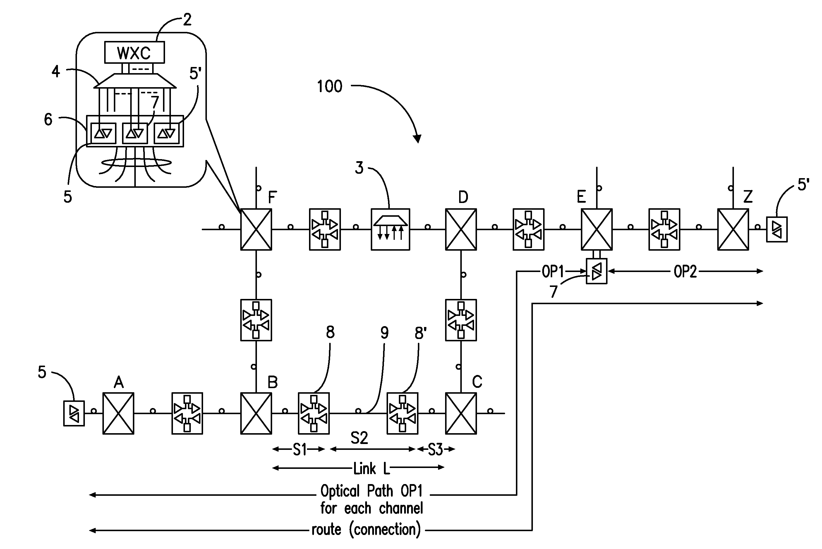
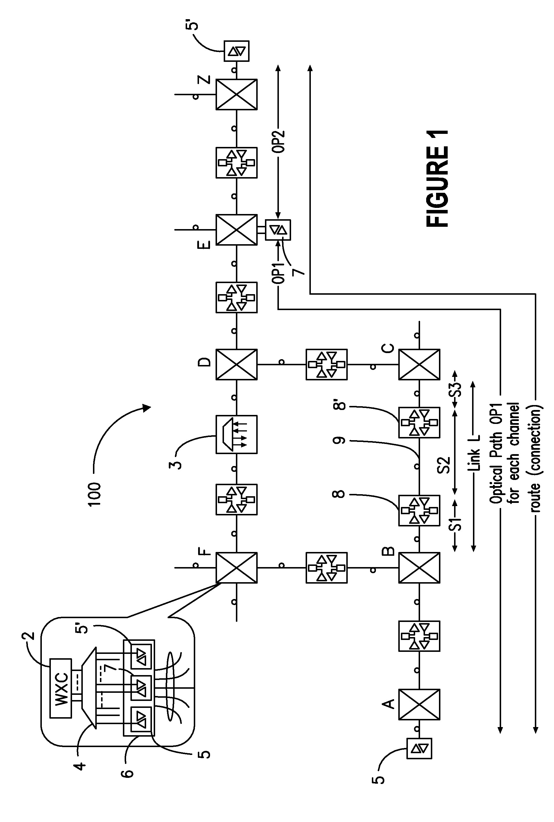
[0037]FIG. 1 illustrates a fragment of an agile optical network 100 for defining some terms used in this specification.

[0038]“Agile optical network” (also referred to as “photonic network”, “all optical network”, “automatically switched optical network ASON”, or “wavelength switched network”) refers to a WDM network, which allows to transparently convey user traffic of various formats on end-to-end (rather than point-to-point) connections. The term ‘connection’ refers here to an end-to-end logical route, which can be set-up along a plurality of physical trails (routes, paths). For example, an A-Z connection transporting traffic between node A and node Z, can be established along an end-to-end trail A-B-C-D-E-Z, or along an alternative end-to-end trail A-B-F-D-E-Z.

[0039]Connection are established in real-time (rather than being pre-provisioned) in agile network 100, the user traffic being automatically switched at all or some intermediate nodes in optical format.

[0040]The term “wavel...


PUM


Abstract

A network operating system NOS for an agile optical network with a plurality of mesh interconnected switching nodes, manages the network using an object-oriented network information model. The model is common to all applications requiring the data stored in the network managed information base. The core model can be expanded for serving specific application areas. The NOS is organized in layers, at the optical module level, connection level and network level. A distributed topology server DTS organizes the physical, logical and topological data defining all network entities as managed objects MO and topology objects TO for constructing a complete network view. The network information model associates a network element NE information model, specified by managed objects MO and a topological information model, specified by topology objects TO. The MOs are abstract specific NE data that define network implementation details and do not include any topological data, while the TOs abstract specific topological data for defining a trail established within the network, and do not include any NE data. The models are associated in a minimal number of points to construct the model of a trial in response to a connection request.

Description

PRIORITY PATENT APPLICATION[0001]Continuation in part of US patent Application “Network operating system with topology autodiscovery” (Emery et al) SN not available yet, filed on Jun. 6, 2002 assigned to Innovance Inc., docket 1015US.RELATED PATENT APPLICATIONS[0002]U.S. patent application Ser. No. 09 / 876,391, “Architecture For A Photonic Transport Network”, (Roorda et al.), filed Jun. 7, 2001, docket #1001 US;[0003]I US patent application “Method for Engineering Connections in a Dynamically Reconfigurable Photonic Switched Network” (Zhou et al.) SN NA, filed May 21, 2002, docket #1010US2.[0004]U.S. patent application Ser. No. 09 / 909,265, “Wavelength Routing and Switching Mechanism for a Photonic Transport Network”, Smith et al., filed Jul. 19, 2001, assigned to Innovance Inc., docket#1021US.[0005]These patent applications are incorporated herein by reference.FIELD OF THE INVENTION[0006]The invention resides in the field of optical communication networks, and is directed in particul...

Claims


Application Information

Patent Timeline
Patent Type & Authority Applications(United States)
IPC IPC(8): H04B10/20H04L12/24H04L29/12H04Q11/00
CPCH04J14/0227H04J14/0278H04L29/12009H04L29/12207H04L41/12H04J14/0228H04Q11/0062H04Q2011/0069H04Q2011/0079H04Q2011/0088H04J14/0241H04L61/20H04L61/50H04L61/00
Inventor FORTIN, GUY CLAUDEMESSENSCHMIDT, MARKUSEMERY, JEFFREY KENNETHLIM, HOCK GINSTEMMER, RALPH
Owner WSOU INVESTMENTS LLC
Why Eureka
Try Eureka