Wave energy harnessing device

a technology of wave energy and harnessing device, which is applied in the field of mechanical energy harnessing device, can solve the problems of limited operation of all other existing systems, and achieve the effect of increasing electrical output and storage capacity, and widening the range of operation

Inactive Publication Date: 2008-09-11
STEVENS INSTITUTE OF TECHNOLOGY
View PDF59 Cites 35 Cited by
  • Summary
  • Abstract
  • Description
  • Claims
  • Application Information

AI Technical Summary

Benefits of technology

[0005]The present invention comprises a system to convert surface wave energy in a body of water into electricity using a buoy-driven electrical generation subsystem, and to deliver the electricity to shore-based utilities. The heavy mechanical components of the electrical generation subsystem are contained in a water-tight housing anchored to the floor of the water body. A cable reel and flotation device enable the system to harness the largest waves recorded on the sea surface. By using winches and anchors, the electrical generation subsystem can be lowered to a safe depth during storms or can be raised near the surface for a shoaling effect in calm seas. The minimum depth of the anchors will be determined by the historic wave climate in the region of operation. This arrangement protects the components of the electrical generation subsystem from the effects of exceptionally large surface waves, such as those generated by large storms and hurricanes.
[0006]The present invention also has a greater range of operation relative to those of existing systems. All other existing systems are operationally limited by wave height. The novel system of the present invention may be designed to be fully operational in waves over 30 meters in height, resulting in an increased electrical output and storage capacity relative to other known existing systems.

Problems solved by technology

All other existing systems are operationally limited by wave height.

Method used


Image

  • Wave energy harnessing device
  • Wave energy harnessing device
  • Wave energy harnessing device

Examples


Embodiment Construction

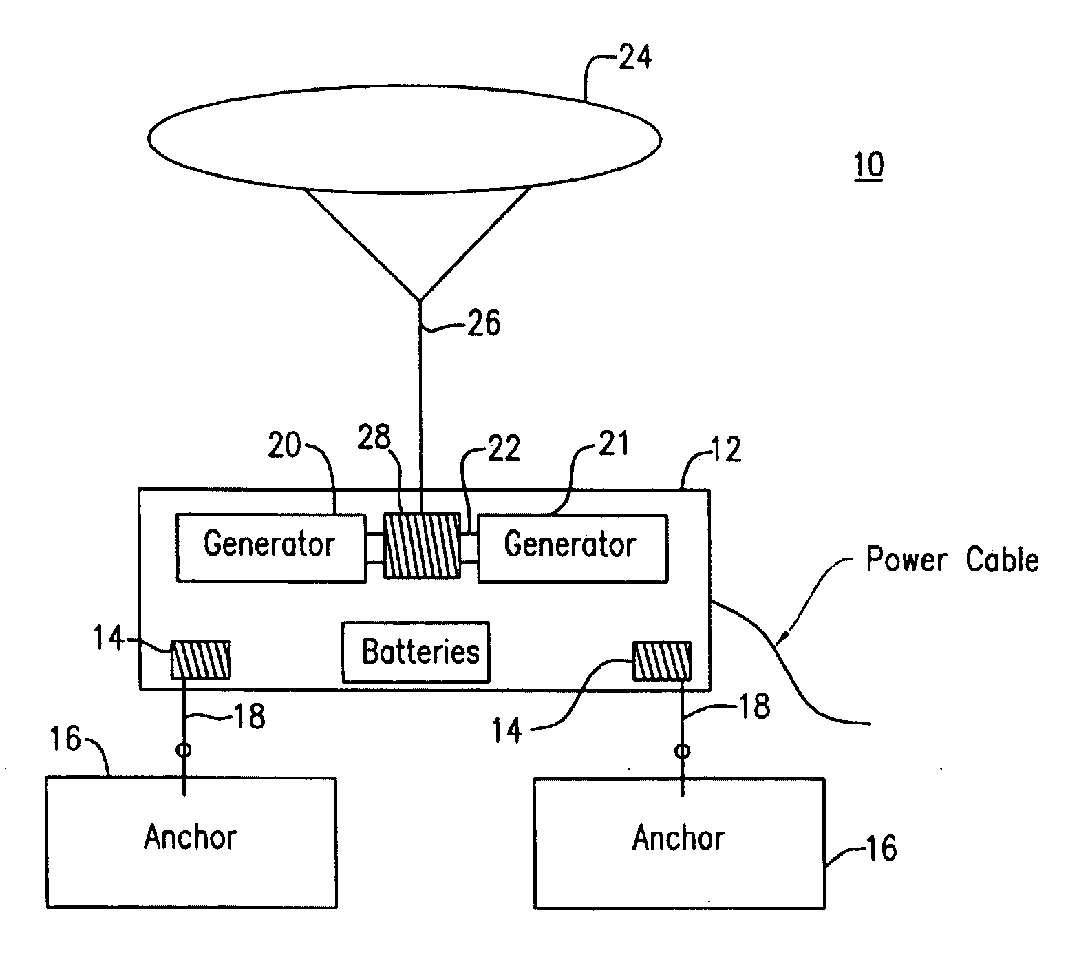
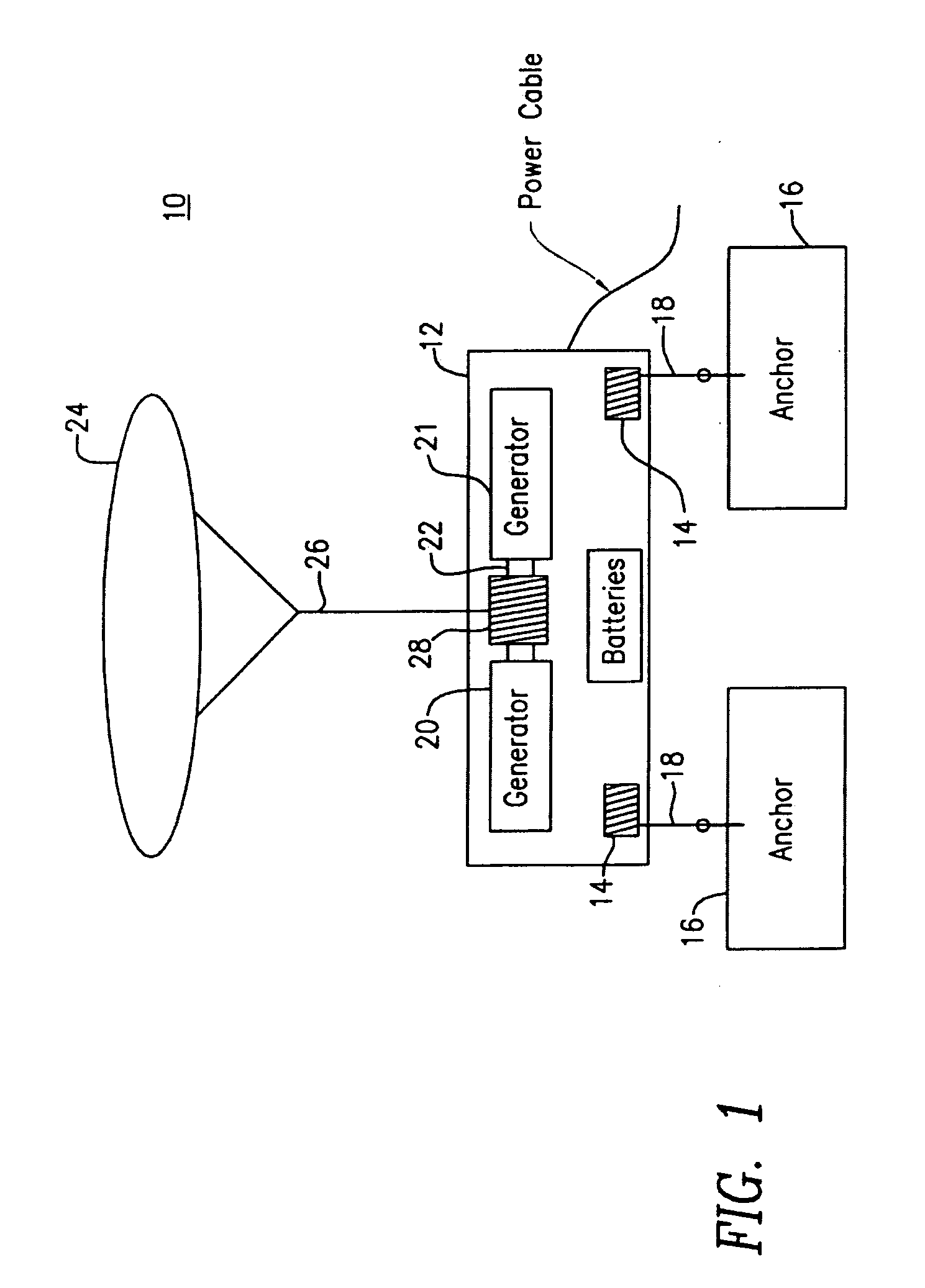
[0010]Turning to FIG. 1, in a preferred embodiment, the present invention 10 includes a water-tight housing 12 that can be lowered and raised by winches 14 connected to anchors 16 by cables 18. The anchors 16 are set in the floor of a body of water such as the ocean. Preferably, the water-tight housing 12 is cylindrical in shape and is anchored at four points. An electrical generation system 20, 21 is contained in the water-tight housing 12 through fittings for power and control cables. The electrical generation system 20, 21 is powered by a shaft 22 fixed or coupled to a cable reel 28, and is connected to power cables to return electrical power to a substation. The shaft 22 may be installed in the housing 12 in the same manner by which a propeller shaft is installed in a boat or submarine. In a typical embodiment, there would be redundant generation systems 20, 21 connected by the shaft 22. The cable reel 28 is tethered to a flotation device 24 on the surface of the water by cable ...


PUM


Abstract

A system for converting fluid surface wave energy into electrical energy. The system includes an electrical generating device, positioned in a waterproof housing, for producing electrical energy. A float, deployed on the fluid surface, is attached to the generating device when the housing is submerged within the fluid. Vertical motion of the surface waves produce vertical motion of the float, which turns and powers the electrical generating device. A plurality of anchors, positioned on the fluid floor, are attached to the housing so that the housing may be positioned proximate the fluid surface for creating a shoaling effect when a plurality of systems are deployed on the fluid surface.

Description

CROSS-REFERENCE TO RELATED APPLICATION[0001]This application is a Section 111(a) application relating to commonly owned, co-pending U.S. Provisional Application Ser. No. 60 / 906,148 entitled “WAVE ENERGY HARVESTING DEVICE” filed Mar. 9, 2007.FIELD OF THE INVENTION[0002]The present invention relates to mechanical energy harnessing devices. Technologies related to this invention fall within the more general fields of Ocean, Mechanical, and Electrical Engineering.BACKGROUND OF THE INVENTION[0003]Systems for converting the mechanical energy of surface waves to electrical power are known to exist. However, the heavy mechanical equipment required to generate electricity is housed in buoys that operate within the dangerous, high-energy region of surface waves. Such arrangements are limited to operating in waves of roughly 15 feet. At greater wave heights, the systems must be put into a lock-down or “survival” mode.[0004]Further, present systems are limited by the technologies used to transm...

Claims


Application Information

Patent Timeline
Patent Type & Authority Applications(United States)
IPC IPC(8): F03B13/14
CPCY02E10/38F03B13/1885Y02E10/30
Inventor RAFTERY, MICHAEL WILLIAM
Owner STEVENS INSTITUTE OF TECHNOLOGY
Why Eureka
Try Eureka