Image projection apparatus

a technology of projection apparatus and projection screen, which is applied in the direction of lighting and heating apparatus, lighting support devices, instruments, etc., can solve the problems of high cost of conventional projection screen and inability to be used

Inactive Publication Date: 2007-02-27
EMERALD INNOVATIONS L L C
View PDF59 Cites 28 Cited by
  • Summary
  • Abstract
  • Description
  • Claims
  • Application Information

AI Technical Summary

Benefits of technology

[0005]This invention overcomes existing drawbacks in the art by providing a projector system including a reflector element with a substantially enclosed drive mechanism. As a result, the drive mechanism is protected from the elements when the projector system is used outdoors.

Problems solved by technology

Drawbacks to the practice of projecting images using light include the high cost of conventional projectors, many of which cannot be used outdoors in inclement weather, and the fact that such projectors typically require some intervention by the user in order to change the image being projected.

Method used


Image

  • Image projection apparatus
  • Image projection apparatus
  • Image projection apparatus

Examples


Embodiment Construction

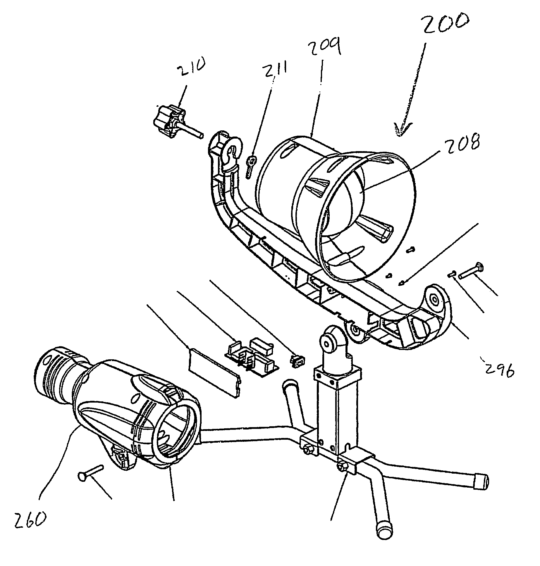
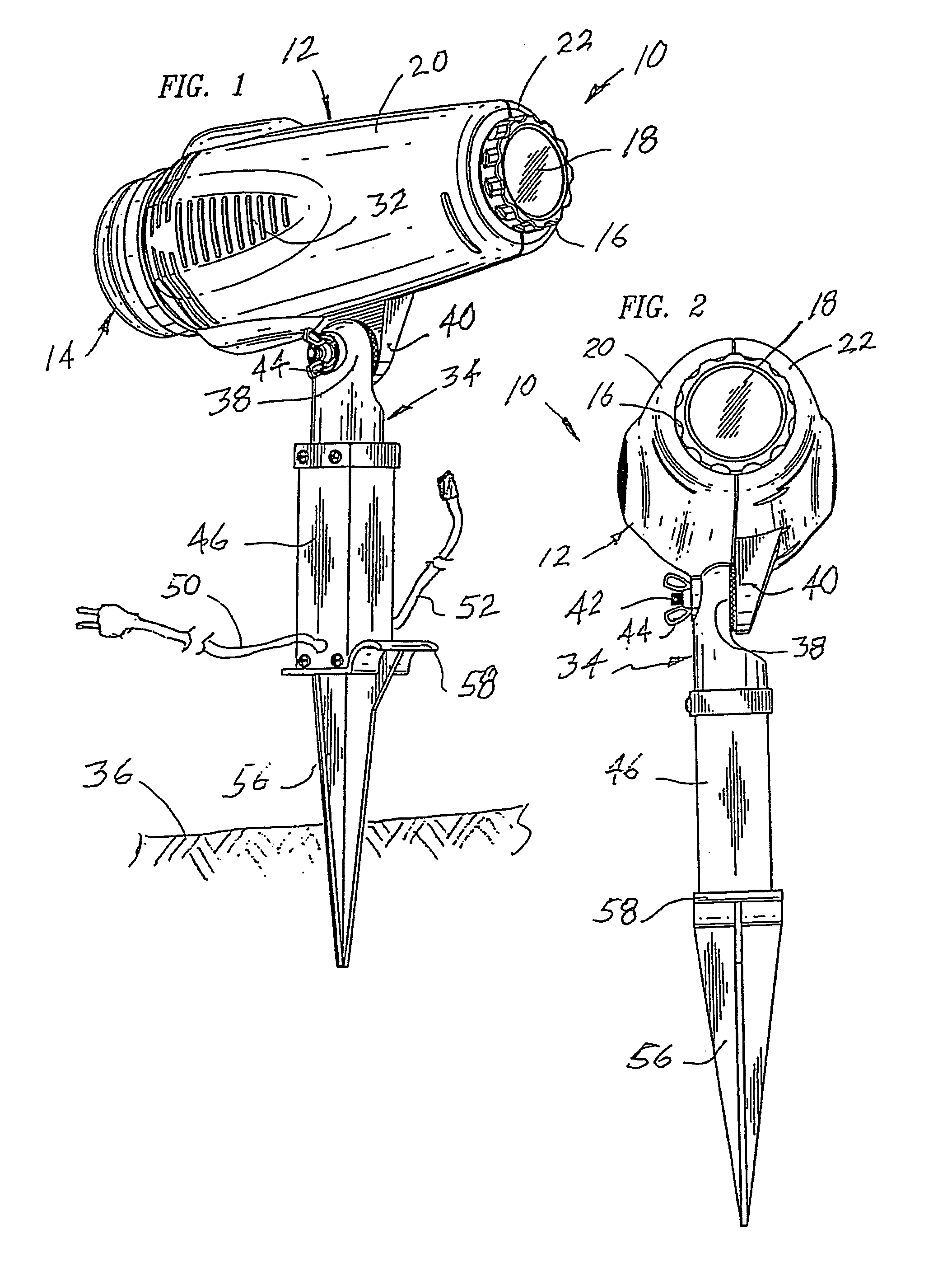
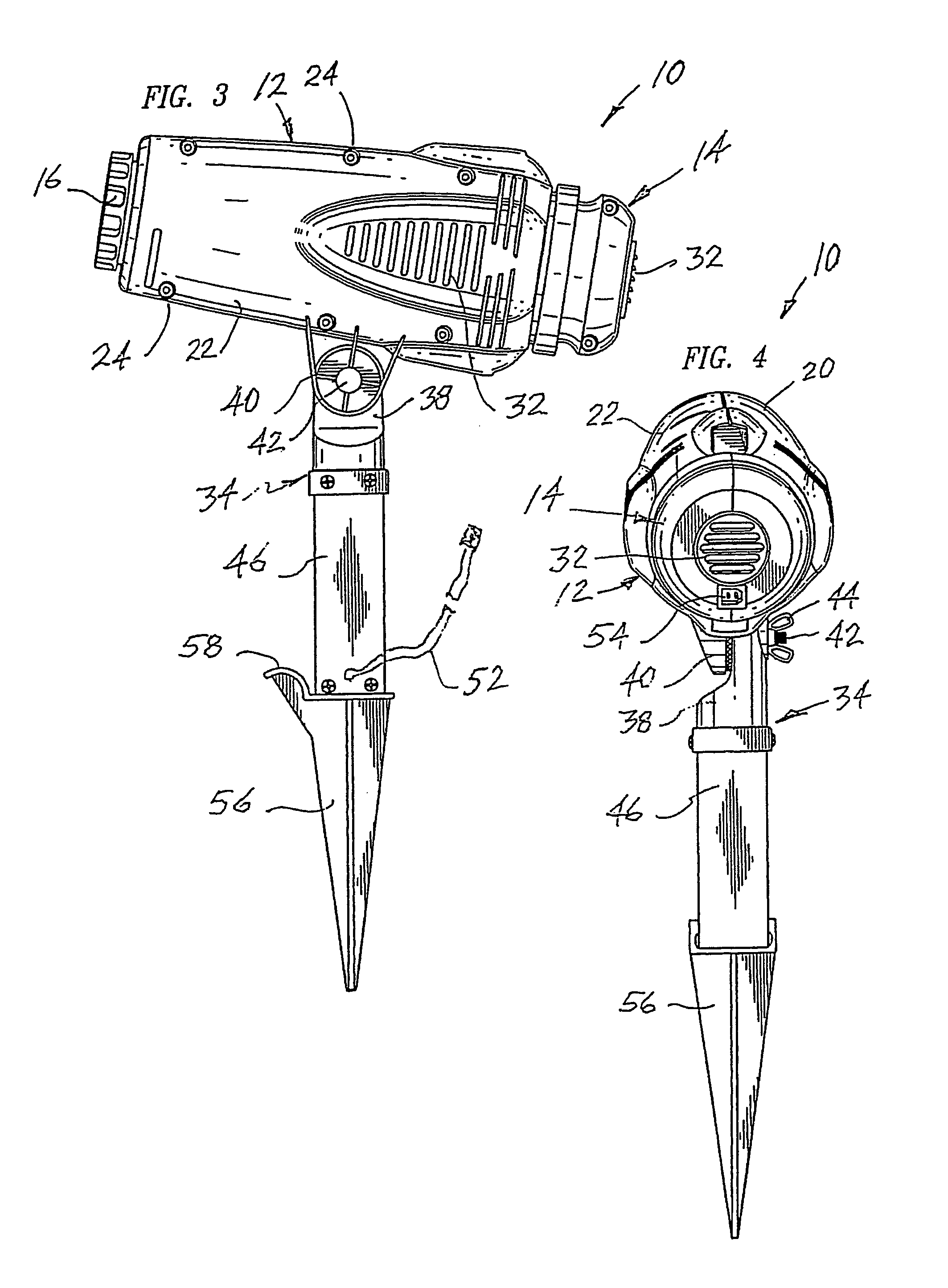
[0037]Referring to FIGS. 1–6, projector 10 preferably comprises a polymeric housing 12 supporting a light source 14 at one end and a lens tube 16, most preferably containing a biconvex lens 18, at the other. Housing 12 is preferably injection molded from an impact resistant polymer and is most preferably molded in two halves 20 and 22 that are joined during assembly with screws 24 or other similarly effective fasteners The imaginary line between light source 14 and lens 18 establishes a light path that, when extended beyond projector 10, continues to a viewing surface upon which an image is to be projected Housing 12 preferably further comprises an image medium support assembly 26 that is disposed between light source 14 and lens 18. Image medium support assembly 26 supports an image medium 28 such as, for example, a circular disk comprising a slide film or transparency in an image window through which light emanating from light source 14 is directed toward lens 18. Lens tube 16 is ...


PUM


Abstract

An image projection apparatus is provided which includes a projector, image source and reflective element. The reflective element is capable of being rotated by a mechanism housed within the reflective element. Light projected from the projector and through the image source is directed to the relective element and reflective onto a surface for viewing. The rotation of the reflective element creates reflected images which move in a desired direction across the viewing surface.

Description

BACKGROUND OF INVENTION[0001]This application is a continuation in part of utility patent application Ser. No. 10 / 008,112 filed on Oct. 22, 2001, which claims priority to U.S. provisional patent application No. 60 / 242,309 filed on Oct. 20, 2000. This application also claims the benefit of U.S. provisional patent application No. 60 / 410,855 filed on Sep. 13, 2002 and U.S provisional patent application No. 60 / 425,455 filed on Nov. 12, 2002.[0002]This invention relates to devices used to project images embodied on transparent polymeric film onto one or more viewing surfaces by shining a light through the image embodied on the film. More particularly, the invention relates to projectors used to project thematic images singly, in either a static or serial display, onto a viewing surface or to project multiple views of an image simultaneously onto a plurality of viewing surfaces.[0003]The projection of images using light is a well known and popular way to decorate or entertain, especially ...

Claims


Application Information

Patent Timeline
Patent Type & Authority Patents(United States)
IPC IPC(8): G03B21/28G03B21/14
CPCF16M11/10F16M11/18F16M11/20G03B23/10F21V21/0824G03B21/14G03B21/28F16M2200/022G03B21/145G03B21/2066
Inventor VITANTONIO, MARC L.JACKSON, TREVORFUTO, DENNISPANASEWICZ, DALE A.NOTTINGHAM, JOHN R.SPIRK, JOHN W.
Owner EMERALD INNOVATIONS L L C
Why Eureka
Try Eureka