Portable Multi Position Magnifier Camera

a multi-position, magnifier technology, applied in the field of magnifier devices, can solve the problems of heavy, bulky, cumbersome use, and little or no room over the object, and achieve the effect of optimizing viewing

Active Publication Date: 2010-02-04
FREEDOM SCI
View PDF57 Cites 27 Cited by
  • Summary
  • Abstract
  • Description
  • Claims
  • Application Information

AI Technical Summary

Benefits of technology

[0008]It is therefore one of the objectives of this invention to allow a user to configure a magnifier camera into one of a variety of viewing modes so as to optimize the viewing of different sized objects at differing distances.

Problems solved by technology

To date, however, these magnifiers have been heavy, bulky, and cumbersome to use.
Additionally, many of these magnifiers have only one mode of operation, a mode that requires the user to hold the device at a fixed distance above the object being viewed.
Additionally, many magnifiers that are designed to be placed upon the object to be viewed typically leave little or no room over top of the object.

Method used


Image

  • Portable Multi Position Magnifier Camera
  • Portable Multi Position Magnifier Camera
  • Portable Multi Position Magnifier Camera

Examples


Embodiment Construction

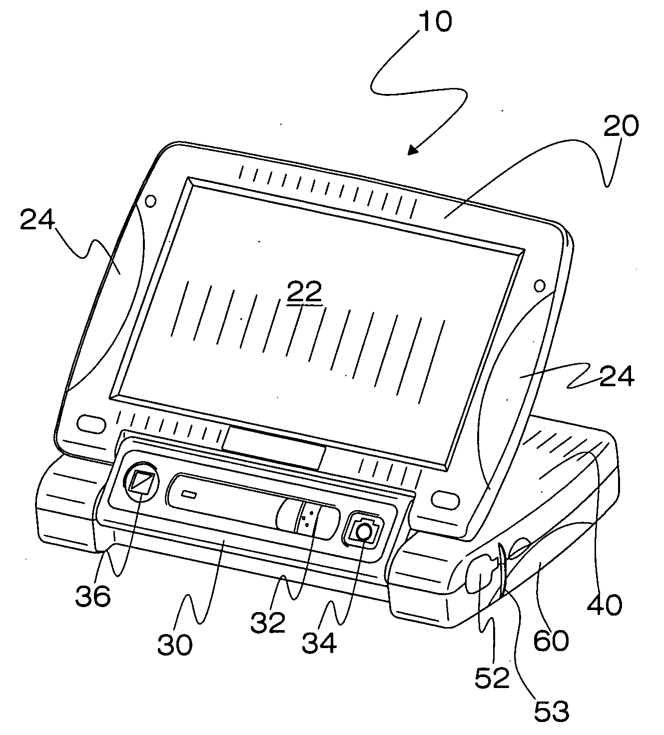
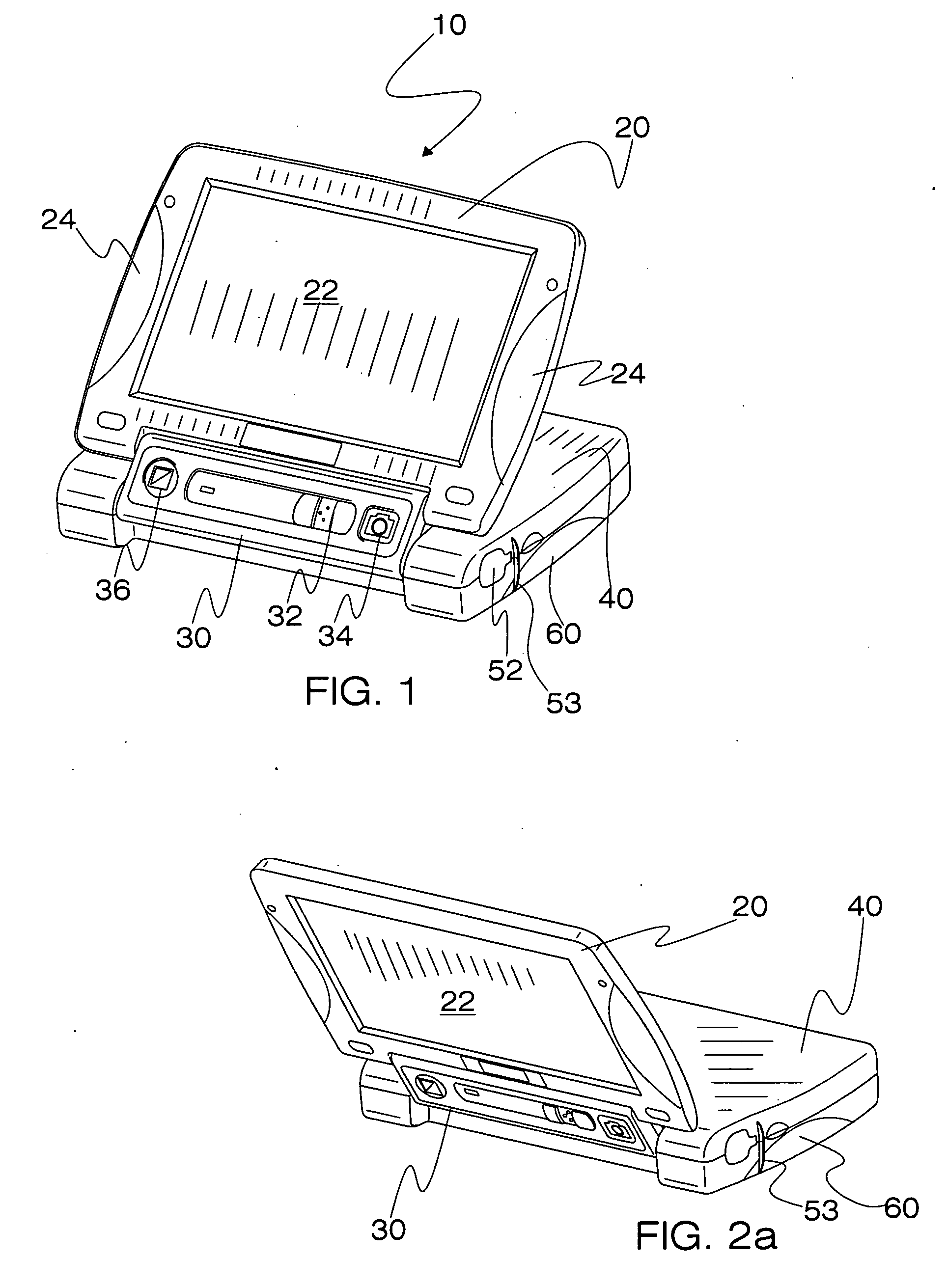
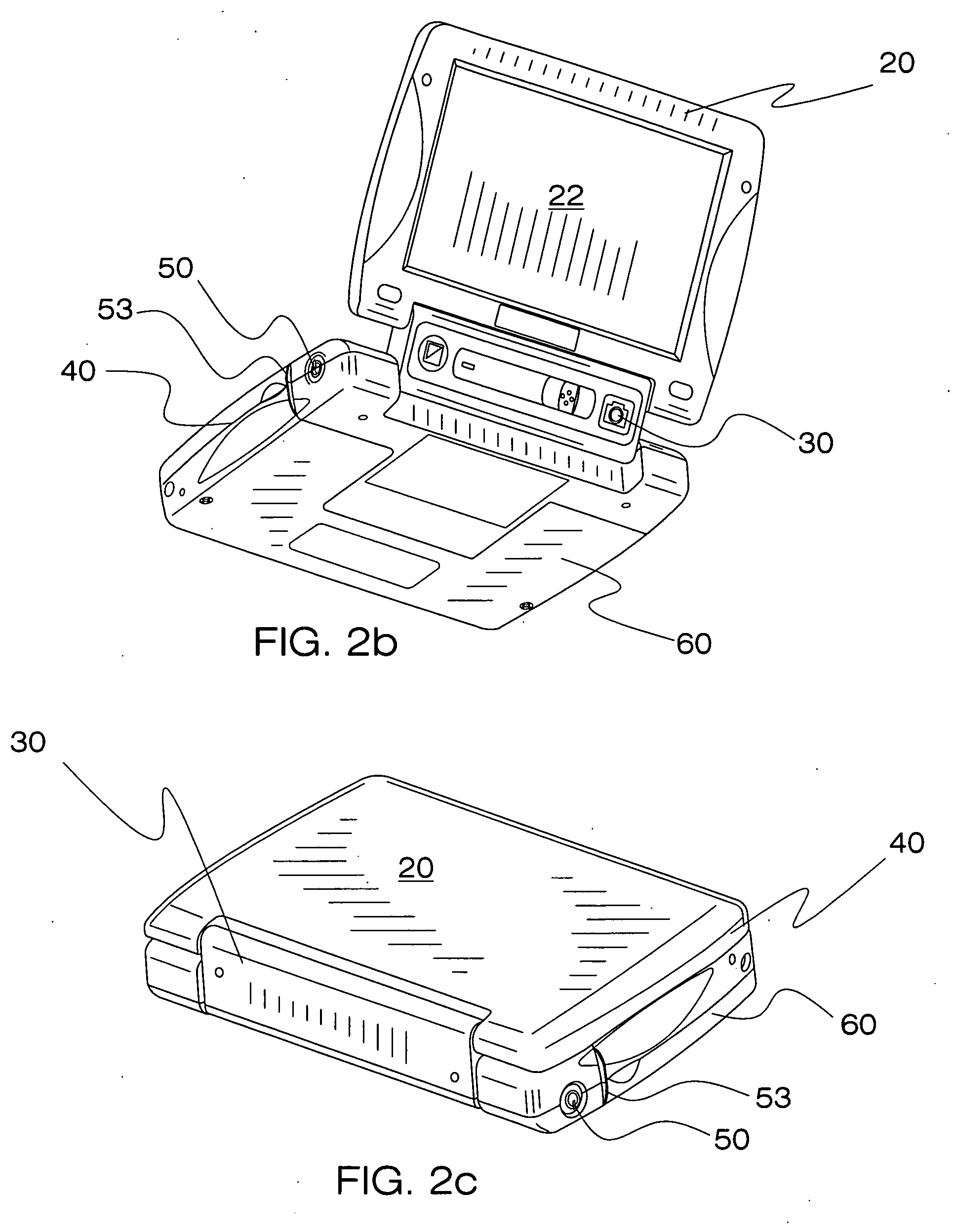
[0027]The present invention relates to portable magnifier camera that can be selectively positioned into a variety of configurations. At least four distinct viewing configurations are provided: a reading mode wherein the camera rests flatly upon the viewed object; a writing mode wherein the camera rests at an angle upon the viewed object; a hand-held mode wherein the user holds the camera relative to a distant object; and an inspection mode wherein the user holds the viewed object in close proximity to the camera. These configurations enable a user to effectively view objects of differing size and at varying distances.

[0028]The camera 10 of the present invention is depicted in FIG. 1. The camera 10 includes four housing components that are pivotally interconnected in a manner that provides for multiple discrete configurations. These housing components include a cover 20, a control panel 30, a camera housing 40, and a base 60. These components are preferably constructed from a lightw...


PUM


Abstract

Disclosed is a portable magnifier camera that can be selectively positioned into a variety of configurations. At least four distinct viewing configurations are provided: a reading mode wherein the camera rests flatly upon the viewed object; a writing mode wherein the camera rests at an angle upon the viewed object; a hand-held mode wherein the user holds the camera relative to a distant object; and an inspection mode wherein the user holds the viewed object relative to the camera. These configurations enable a user to effectively view objects of differing size and at varying distances.

Description

CROSS REFERENCES TO RELATED APPLICATIONS [0001]This application claims benefit of co-pending application Ser. No. 61 / 085,966 filed on Aug. 4, 2008 and entitled “Portable Multi Position Magnifier Camera.” The contents of this application are incorporated herein by reference.BACKGROUND OF THE INVENTION [0002]1. Field of the Invention[0003]This invention relates to a magnification device for individuals with low vision. More particularly, the present invention relates to a portable magnification device that has a variety of discrete configurations.[0004]2. Description of the Background Art[0005]The use of portable magnifiers for low vision users is known in the art. To date, however, these magnifiers have been heavy, bulky, and cumbersome to use. Additionally, many of these magnifiers have only one mode of operation, a mode that requires the user to hold the device at a fixed distance above the object being viewed.[0006]Additionally, many magnifiers that are designed to be placed upon ...

Claims


Application Information

Patent Timeline
Patent Type & Authority Applications(United States)
IPC IPC(8): H04N5/262H04N5/225
CPCH04N1/195H04N1/19594H04N5/2252H04N2201/045H04N2201/043H04N2201/0436H04N5/2256H04N23/56H04N23/51
Inventor RODRIGUEZ, CARLOS M.MURPHYTUNKIS, WALDEMARDAVIS, BRADCONARD, TODDHAMILTON, LEEGOLDENBERG, MICHAELMCDANIEL, JEFFREY
Owner FREEDOM SCI
Why Eureka
Try Eureka