
Protective cover support rack for portable electronic devices

a technology for supporting racks and electronic devices, applied in the field of protective cover support racks for electronic devices, can solve the problems of inconvenient and troublesome, inconvenient storage, and easy scraping of the surface of the cover, and achieve the effect of convenient viewing, storage and holding

Inactive Publication Date: 2012-07-31
E LEAD ELECTRONICS
View PDF22 Cites 98 Cited by
  • Summary
  • Abstract
  • Description
  • Claims
  • Application Information

AI Technical Summary

Benefits of technology

[0007]In view of the aforesaid problems occurred to the conventional portable electronic device, the primary object of the present invention is to provide a protective cover support rack for portable electronic devices to protect the screen of an electronic device, support it in a standing manner to facilitate viewing and also make storing and holding easier.
[0008]To achieve the foregoing object, the invention includes at least a protective cover body, a support lid and a hinge assembly. The protective cover body has an inner rim with an annular U-shaped trough formed thereon to hold and encase the body of an electronic device, and a lower half portion to cover the back side of the electronic device. The hinge assembly includes two hinge means each has one end fastened to one lateral side of the protective cover body and another end fastened to the bottom side of the support lid. Thereby the support lid can be adjusted in a space at an angle smaller than 360 degrees to allow users to swivel to the front side to protect the screen of the electronic device, or adjust to a standing position to facilitate viewing, or fold it to fully in contact with back side of the protective cover body for storing, or swivel to facilitate hand grasping in use, thus provide diversified usages and improve practicality.
[0009]The protective cover body includes an upper half portion and a lower half portion that are coupled together. The upper half portion is made from a hard material (such as plastics, ABS, PC, metal or the like) to provide desirable support strength to bear the weight of the electronic device. The lower half portion is made from a pliable material (such as rubber, leather or the like) that is resilient to facilitate coupling of the electronic device with the protective cover body.
[0010]The support lid has a bottom side fastened to the hinge means and another side formed a grip aperture to facilitate insertion of user's fingers for grasping. The grip aperture is formed at a width greater than 3 cm and longer than 8 cm. Hence when the support lid is flipped outwards to a horizontal position or close to the horizontal position, user' fingers can insert into for grasping to alleviate the burden of user's arm and make operation of the electronic device easier.

Problems solved by technology

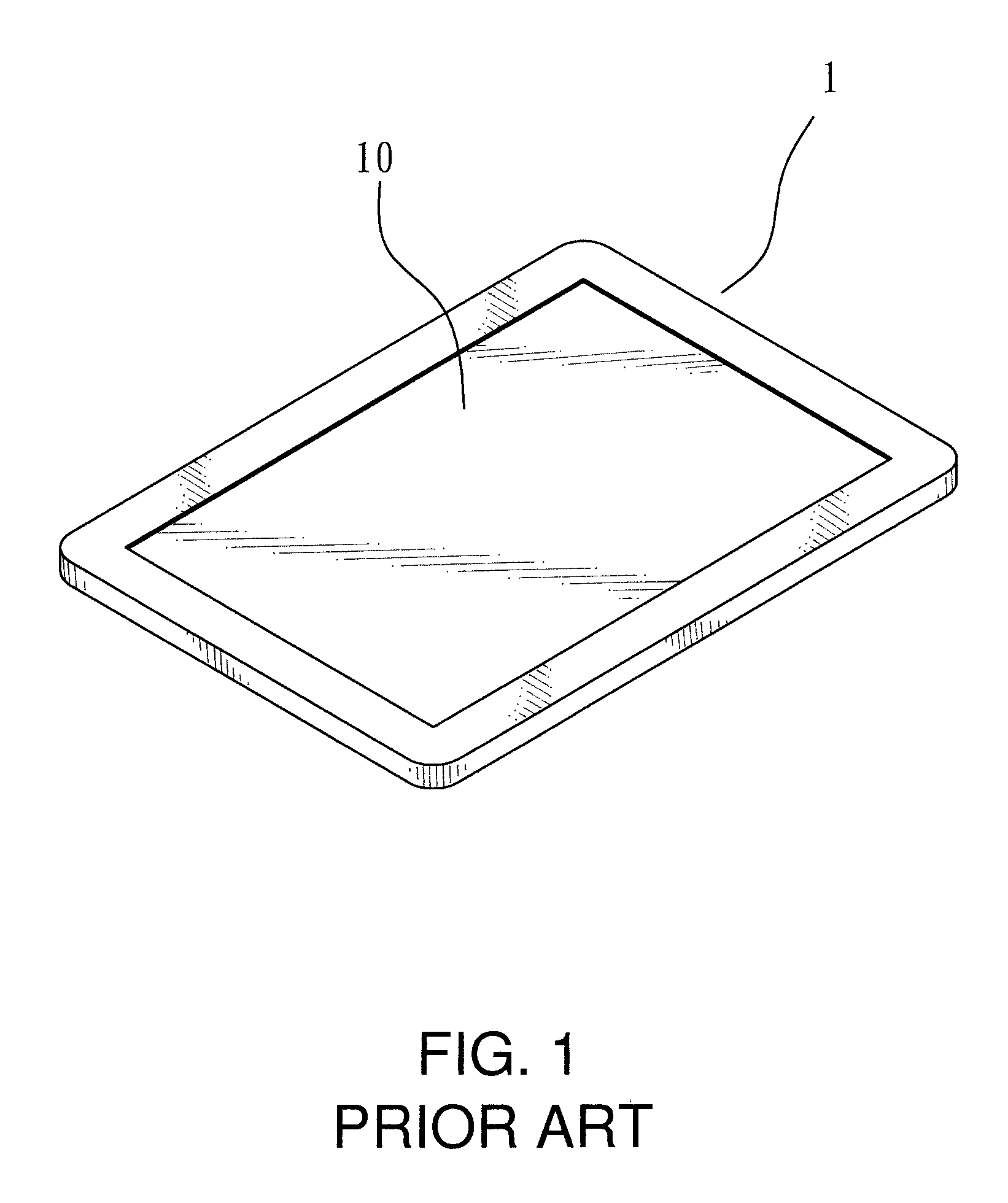
While the portable electronic device 1 is simply structured and very neat in profile, and often creates a great appeal to the users, its surface is prone to be scraped or smeared and results in an undesirable aesthetic appearance.
It is inconvenient and troublesome, and easily causes physical fatigue of user's hands when used in a prolonged duration.
This also tends to cause fatigue of the hands in a long duration.
In addition, the portable electronic device 1 is mostly designed with a streamline and smooth profile to enhance aesthetic appeal, that makes hand holding even more difficult.
This increases the load of the hand and reduce the sustainable time of the hand, and also increases the fatigue and burden of user's hands and arms.

Method used


Image

  • Protective cover support rack for portable electronic devices
  • Protective cover support rack for portable electronic devices
  • Protective cover support rack for portable electronic devices

Examples


Embodiment Construction

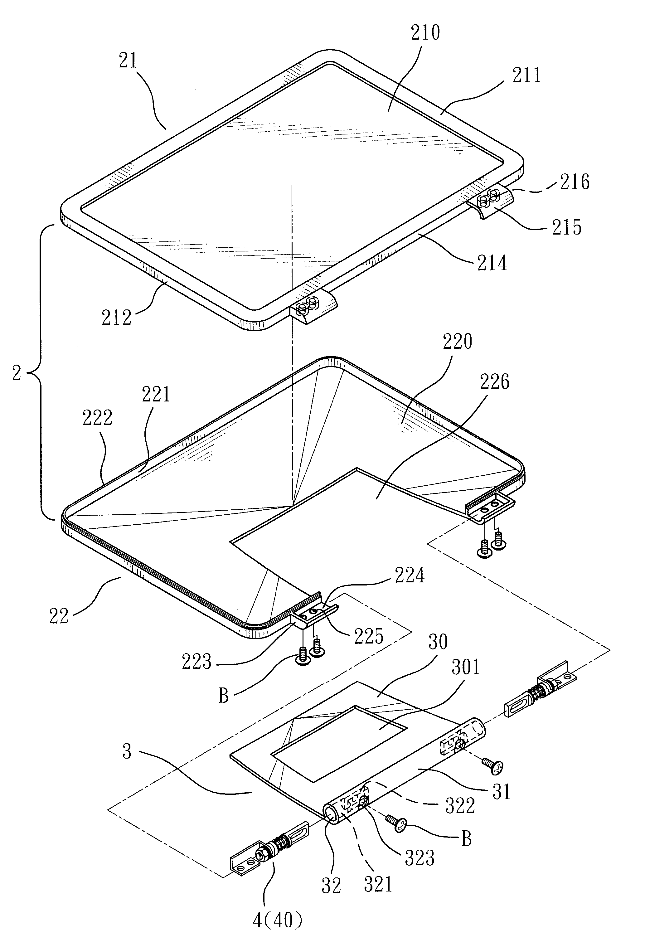
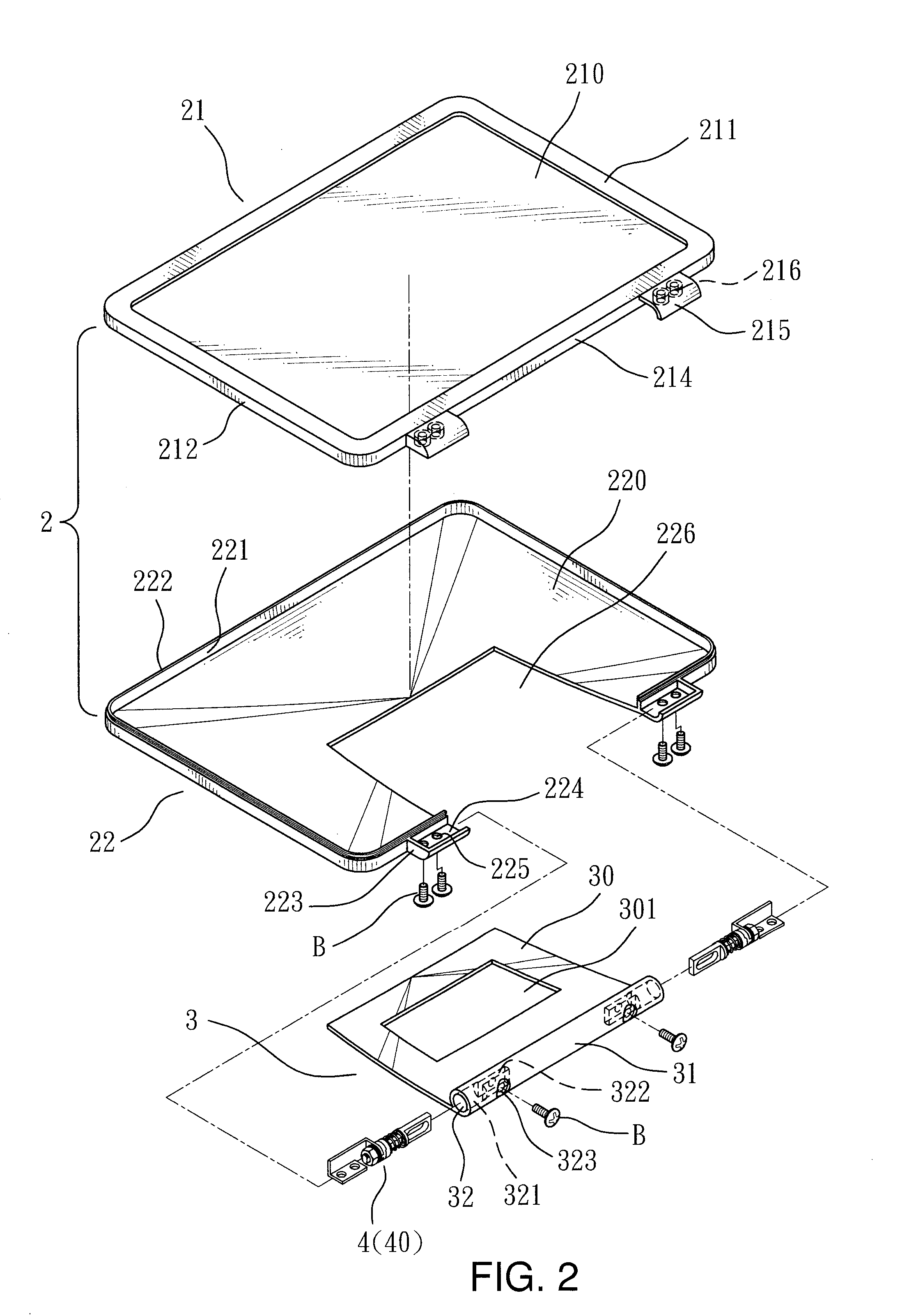
[0024]Referring to FIGS. 2 and 3, the invention includes at least a protective cover body 2, a support lid 3 and a hinge assembly 4.

[0025]The protective cover body 2 includes an upper half portion 21 with a frame 211 and a view window 210 formed thereon, and an inner rim with an annular U-shaped trough A formed thereon to hold and encase the body of an electronic device 5, and a lower half portion 22 to cover the back side of the electronic device 5. The lower half portion 22 further has at least one storing notch 226.

[0026]The support lid 3 has a bottom side 31 with two ends formed respectively a pivotal portion 32. The bottom side 31 has one edge extended to form a lid plate 30 which has a grip aperture 301 formed thereon.

[0027]The hinge assembly 4 includes two hinge means 40. Each hinge means 40 has one end fastened to a lateral side D of the protective cover body 2 and another end held in the pivotal portion 32 of the support lid 30.

[0028]The protective cover body 2 further incl...


PUM


Abstract

A protective cover support rack for electronic devices includes at least a protective cover body, a support lid and a hinge assembly. The protective cover body has an inner rim with an annular U-shaped trough formed thereon to hold and encase the body of an electronic device, and a lower half portion to cover the back side of the electronic device. The support lid can be adjusted at an angle smaller than 360 degrees to allow users to swivel to the front side as required to protect the screen of the electronic device, or adjust to a standing position to facilitate viewing, or fold it to fully in contact with back side of the protective cover body at a storing position, or swivel to facilitate hand grasping in use.

Description

BACKGROUND OF THE INVENTION[0001]1. Field of the Invention[0002]The present invention relates to a protective cover support rack for electronic devices and particularly to a protective cover support rack to protect the screen of an electronic device or support its standing and also is foldable quickly for storing and extendable to serve as a handle to enhance use diversity and improve practicality.[0003]2. Description of the Prior Art[0004]Computers have advanced greatly in recent years, evolving from a bulky set housed in a computer room to become personal computers and notebook computers, and now become touch control portable electronic device 1 (referring to FIG. 1), such as smart phones, tablet computers, smart handsets and the like. It generally has a touch screen 10 allowing users to directly select targeted items intuitively on the computer screen, and with two or more fingers splaying or closing to zoom the icons or texts on the screen larger or smaller. The touch screen pro...

Claims


Application Information

Patent Timeline
Patent Type & Authority Patents(United States)
IPC IPC(8): A47G29/00
CPCF16M11/10F16M11/105F16M13/00G06F1/1626G06F1/166Y10S248/917
Inventor CHEN, STEPHEN
Owner E LEAD ELECTRONICS
Learn More