Refrigerator with air guide duct

a technology of refrigerator and guide duct, which is applied in the field of refrigerators, can solve the problems of deteriorating convection-heat transfer efficiency for evaporation of defrost water, slow air flowing above the surface of defrost water, and parts of the machine room may not be efficiently arranged, so as to minimize the space occupied by the evaporating dish and improve the evaporation efficiency of defrost water

Active Publication Date: 2008-09-18
SAMSUNG ELECTRONICS CO LTD
View PDF3 Cites 22 Cited by
  • Summary
  • Abstract
  • Description
  • Claims
  • Application Information

AI Technical Summary

Benefits of technology

[0010]Accordingly, it is an aspect of the present embodiment to provide a refrigerator capable of minimizing a space occupied by an evaporating dish and improving evaporation efficiency of defrost water by convection-heat transfer.
[0011]It is another aspect of the present embodiment to provide a refrigerator capable of improving the cooling efficiency of a compressor and a condenser by facilitating air exhaustion in a machine room.

Problems solved by technology

However, in such a refrigerator, since the air flowing toward the evaporating dish by the cooling fan is diffused inside the machine room, the speed of air flowing above the surface of the defrost water becomes slow, and thus the convection-heat transfer efficiency for evaporation of the defrost water is deteriorated.
However, in such a case, since a space occupied by the evaporating dish in the machine room increases, the parts of the machine room may not be efficiently arranged.
Further, airflow may interfere with the evaporating dish.
Moreover, in such a refrigerator, since the air blown by the cooling fan is diffused inside the machine room, the air is not easily exhausted from the machine room.
This may decrease the cooling efficiency of the compressor and the condenser, resulting in efficiency deterioration.

Method used


Image

  • Refrigerator with air guide duct
  • Refrigerator with air guide duct
  • Refrigerator with air guide duct

Examples


Embodiment Construction

[0025]Reference will now be made in detail to the embodiment, examples of which are illustrated in the accompanying drawings, wherein like reference numerals refer to the like elements throughout. The embodiment is described below to explain the present invention by referring to the figures.

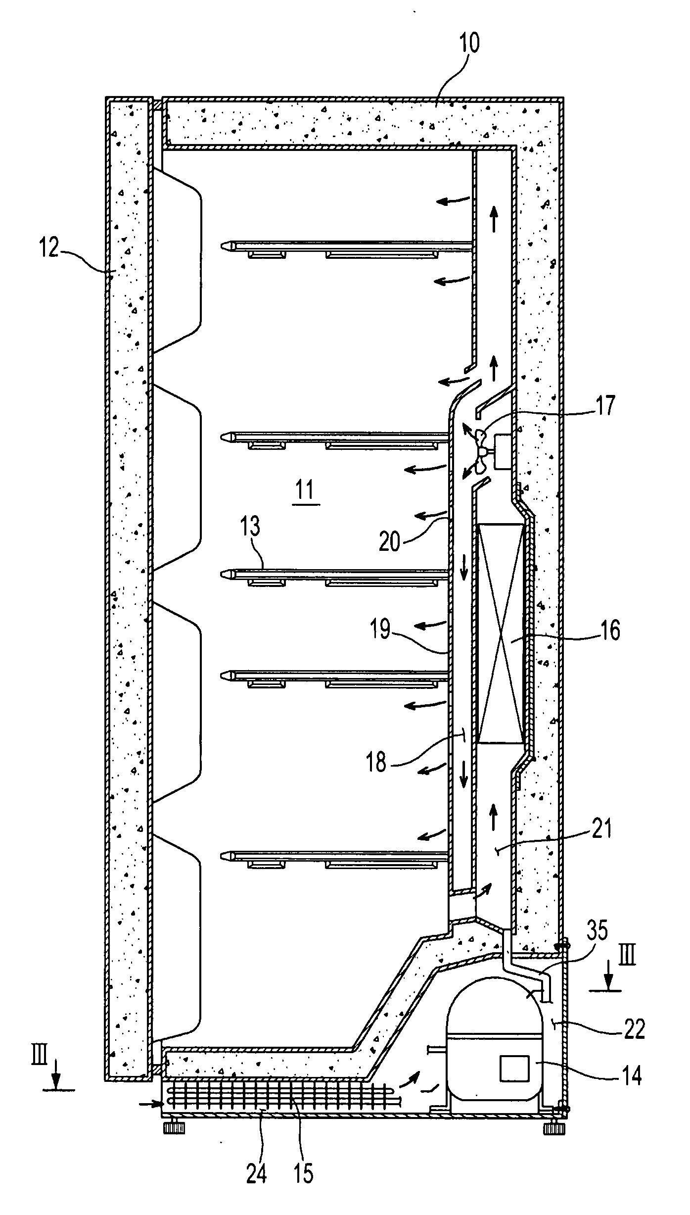
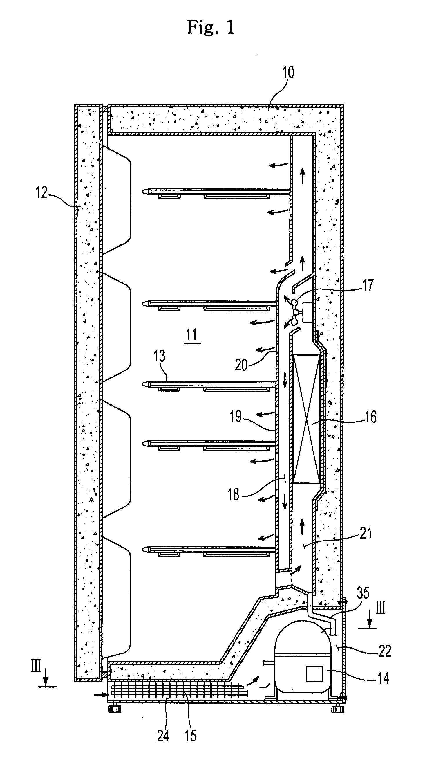
[0026]As illustrated in FIG. 1, a refrigerator according to the present embodiment includes a body 10 having a storing chamber 11 to store foods, etc. The storing chamber 11 has an opened front surface, and a front surface of the body 10 is provided with a door 12 to open or close the storing chamber 11. The storing chamber 11 has a plurality of shelves 13 to store goods or foods in multiple rows.

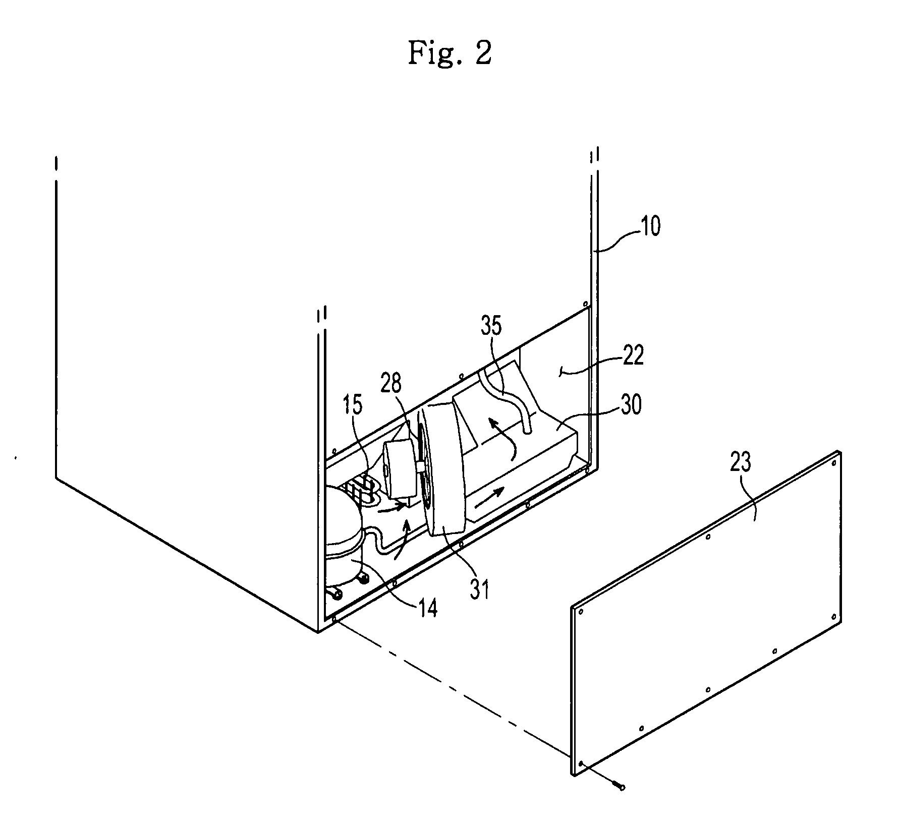
[0027]The storing chamber 11 is cooled by a cooling apparatus. The cooling apparatus includes a compressor 14 compressing refrigerant, a condenser 15 condensing the compressed refrigerant, an expander (not shown) expanding the condensed refrigerant in a low pressure, and an evaporator 16 evaporating the ...


PUM


Abstract

Disclosed is a refrigerator in which a space occupied by an evaporating dish can be minimized, evaporation efficiency of defrost water by convection-heat transfer can be improved, air can be easily exhausted in a machine room, and thus the cooling efficiency of a compressor and a condenser can be improved. The refrigerator includes: a cooling apparatus including a compressor, a condenser, and an evaporator; a blowing fan blowing air to cool at least one of the compressor and the condenser; a blowing guide duct guiding the air blown by the blowing fan to an exterior; and an evaporating dish installed in a lower portion of the blowing guide duct in order to collect and evaporate defrost water, the evaporating dish having an opened upper portion to communicate with a path of the blowing guide duct.

Description

CROSS-REFERENCE TO RELATED APPLICATIONS[0001]This application claims the benefit of Korean Patent Application No. 10-2007-0024222, filed on Mar. 12, 2007, in the Korean Intellectual Property Office, the disclosure of which is incorporated herein by referenceBACKGROUND[0002]1. Field[0003]The present invention relates to a refrigerator, and more particularly, to a refrigerator capable of improving evaporation efficiency of defrost water.[0004]2. Description of the Related Art[0005]A refrigerator has a cooling apparatus to cool a storing chamber. Conventionally, a cooling apparatus of a refrigerator includes a compressor compressing refrigerant, a condenser condensing the compressed refrigerant, an expander expanding the condensed refrigerant, and an evaporator evaporating the expanded refrigerant to cool the storing chamber.[0006]Since the compressor and the condenser must cool the storing chamber using external air, they are installed in a machine room separated from the storing cham...

Claims


Application Information

Patent Timeline
Patent Type & Authority Applications(United States)
IPC IPC(8): F25D21/14F25D21/00
CPCF25D21/14F25D23/003F25D2321/1442F25D2323/00282F25D2323/0021F25D2323/00264F25D2323/00274F25D2321/146
Inventor JEONG, JINMIN, JUNE KEEPARK, YONG PILLEE, SUNG GYOULIM, CHANG HAKLEE, IN SUBYOON, WON JAEKIM, YONG HANJUNG, YEO WOOL
Owner SAMSUNG ELECTRONICS CO LTD
Why Eureka
Try Eureka