
Support stand for a bicycle

a technology for supporting or supporting a bicycle, which is applied in the direction of bicycle stands, cycle equipment, applications, etc., can solve the problems of bicycle damage, bicycle does not have a kickstand, and most racing bicycles are not equipped with a kickstand

Inactive Publication Date: 2005-03-22
GRABER PRODS INC
View PDF19 Cites 24 Cited by
  • Summary
  • Abstract
  • Description
  • Claims
  • Application Information

AI Technical Summary

Benefits of technology

It is an object of the present invention to provide a stand or support for a bicycle or the like, which is adapted to be placed on the ground or other supporting surface for temporarily maintaining the bicycle in an upright position. Another object of the invention to provide such a stand or support which has a compact, lightweight design to facilitate storage and transportation from one location to another. It is a further object of the invention to provide such a stand or support which can be collapsed, so as to minimize the space occupied by the stand or support for storage and transportation. Yet another object of the invention is to provide such a stand or support which can be adjusted so as to allow use in connection with bicycles having tires of varying widths. Yet another object of the invention is to provide such a stand or support which is relatively simple in its construction and operation, and which is capable of being moved to various locations and reliably supporting the bicycle in an upright position.
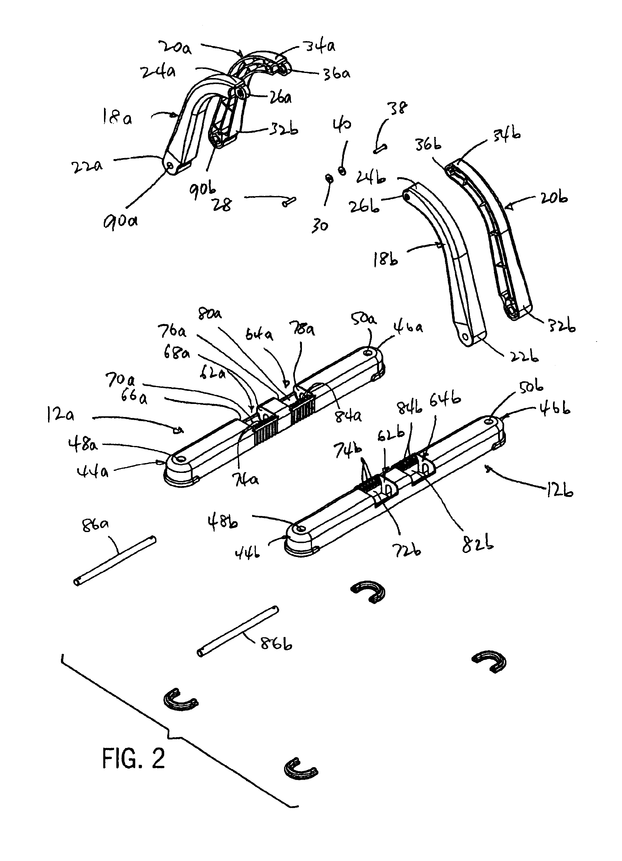
An adjustment arrangement is interposed between at least one of the support members and each of the pair of base members, to enable the lateral spacing between the support members to be adjusted so as to accommodate different wheel widths. In the disclosed embodiment, the adjustment arrangement includes a laterally extending guide member associated with each base member, and the lower area of one of the support member sections is laterally movable via engagement with the guide member. A variable position engagement arrangement is interposed between the base member and the lower end of the support member section, for selectively fixing the lateral position of the support member relative to the base member. The variable position engagement arrangement is preferably in the form of engagement structure interposed between the lower end of the support member section and the base member to which the support member section is mounted. Each base member is movably mounted to the lower end of one of the support member sections, e.g. via a pivot connection, for movement between an operative locking position and an inoperative release position. When the base member is in the operative locking position, the variable position engagement arrangement is operable to prevent lateral movement of the support member section, to thereby fix the lateral spacing between the support members. When the base member is moved to its inoperative release position, the lateral position of the support member section can be adjusted relative to the base member so as to adjust the spacing between the support members. Subsequent return of the base member to its operative locking position functions to maintain the support members in the adjusted position.

Problems solved by technology

In many cases, however, a bicycle does not have a kickstand, such as when the bicycle is on display for sale or exhibition.
In addition, most racing bicycles are not equipped with a kickstand.
Either situation is undesirable and can result in damage to the bicycle.
Stationary bicycle racks can be used to support such bicycles, but do not have the mobility required to support a bicycle when the bicycle is moved to various locations.

Method used


Image

  • Support stand for a bicycle
  • Support stand for a bicycle
  • Support stand for a bicycle

Examples


Embodiment Construction

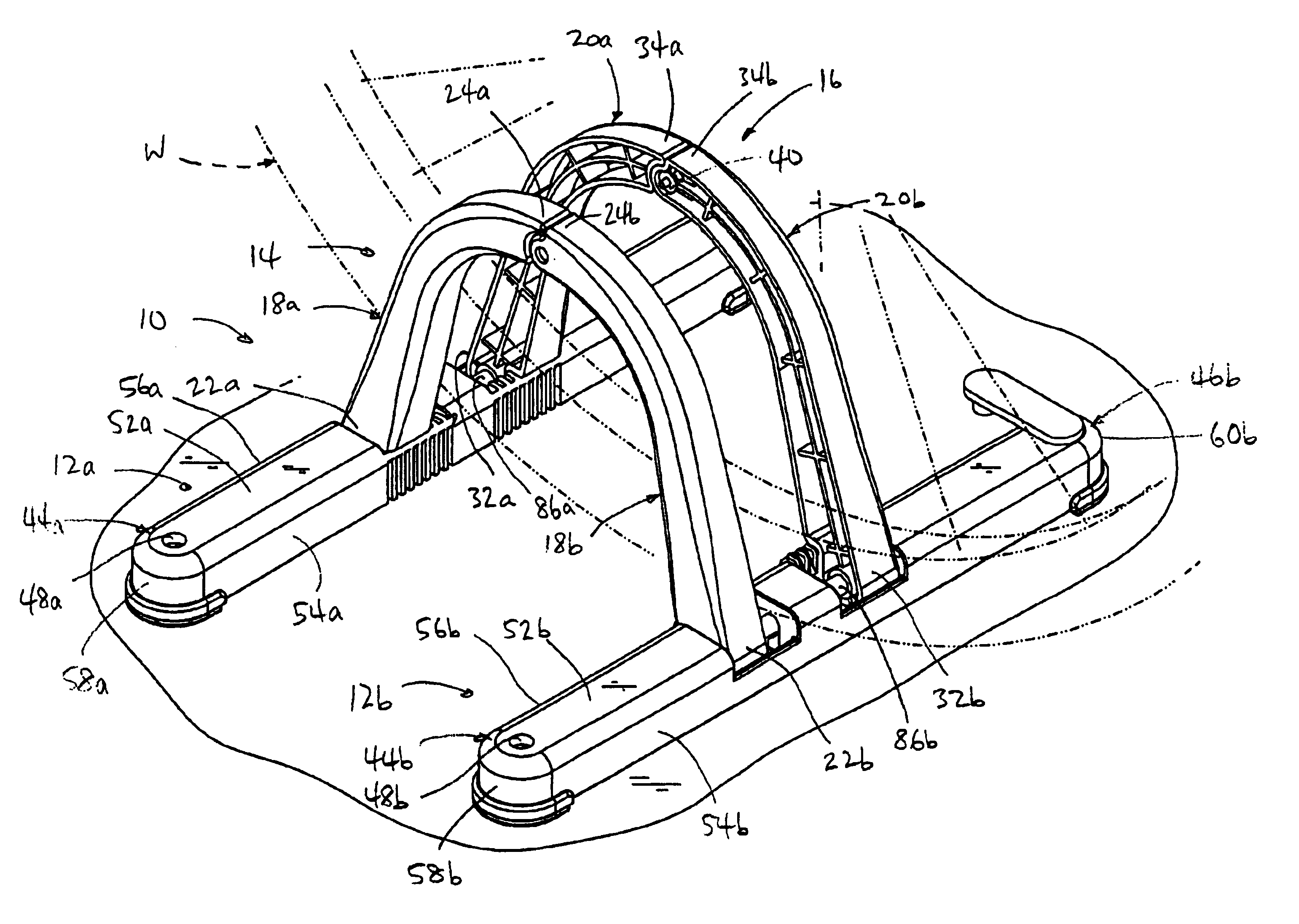
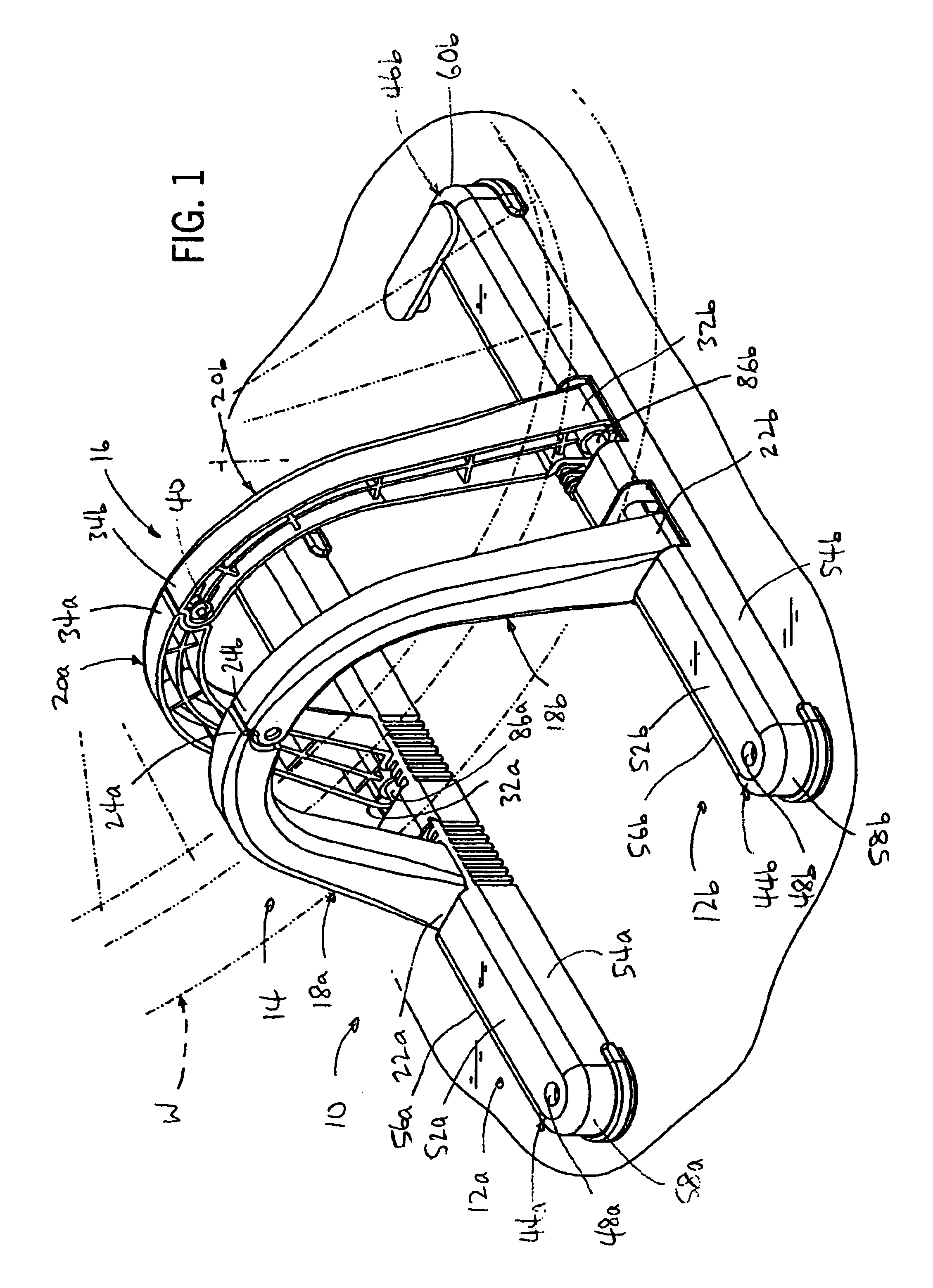
Referring to FIG. 1, a stand or support 10 for a bicycle or the like generally includes a base arrangement and a pair of laterally spaced apart uprights which are adapted to receive one wheel (W) of a bicycle therebetween, for supporting the bicycle in an upright position. Support 10 can be used in any environment in which it is desired to support a bicycle or the like, such as for storage; display, packing in a garage or at a race site, etc.

The base arrangement of support 10 is in the form of a pair of identically constructed base members 12a, 12b, and the uprights of support 10 are in the form of a pair of mirror image support members 14 and 16 that are engaged with and extend upwardly from and between base members 12a, 12b. Support member 14 is made up of a pair of support member sections 18a, 18b, and support member 16 is made up of a pair of support member sections 20a, 20b. Base members 12a and 12b are adapted for engagement with a support surface such as the ground, a floor o...


PUM


Abstract

A support for a bicycle having at least one wheel includes a pair of axially spaced apart base members, and a pair of laterally spaced apart support members which extend upwardly from and which are interconnected with the base members. The bicycle wheel is adapted for placement between the support members, which are configured to support the bicycle in an upright position. Engagement of the bicycle wheel with the base members prevents the bicycle wheel from rolling, to maintain the bicycle in engagement with the support. A variable position engagement arrangement is provided between at least one of the support members and the base members, to enable adjustment in the lateral spacing between the support members so as to accommodate different wheel widths. The support members may be formed of pivotably interconnected sections, which enable the support to be moved between an extended position for use and a collapsed position for shipment, transport or storage.

Description

BACKGROUND AND SUMMARY OF THE INVENTIONThis invention relates to a support or stand for supporting a bicycle or the like in an upright position.It is common to utilize a kickstand for maintaining a bicycle or the like in an upright position when not in use. In many cases, however, a bicycle does not have a kickstand, such as when the bicycle is on display for sale or exhibition. In addition, most racing bicycles are not equipped with a kickstand. When not in use, such bicycles are typically leaned up against a support, such as a building or vehicle, or laid upon the ground. Either situation is undesirable and can result in damage to the bicycle. Stationary bicycle racks can be used to support such bicycles, but do not have the mobility required to support a bicycle when the bicycle is moved to various locations.It is an object of the present invention to provide a stand or support for a bicycle or the like, which is adapted to be placed on the ground or other supporting surface for ...

Claims


Application Information

Patent Timeline
Patent Type & Authority Patents(United States)
IPC IPC(8): B62H3/08B62H3/00
CPCB62H3/08
Inventor LASSANSKE, TODD W.PIN, CHANG SHIN
Owner GRABER PRODS INC
Learn More