
Rear peep sight for mounting to a bow string, having interchangeable sight ports for accommodating user preferences

a rear peep sight and bow string technology, applied in the direction of sighting devices, white arms/cold weapons, weapons, etc., can solve the problem of not being suitable for the purpos

Inactive Publication Date: 2006-05-09
SHAFFER ALFRED H +1
View PDF22 Cites 48 Cited by
  • Summary
  • Abstract
  • Description
  • Claims
  • Application Information

AI Technical Summary

Benefits of technology

[0013]ACCORDINGLY, AN OBJECT of the present invention is to provide a rear peep sight for mounting to a string of a bow and having interchangeable sight ports for accommodating different user preferences that avoids the disadvantages of the prior art.
[0014]ANOTHER OBJECT of the present invention is to provide a rear peep sight for mounting to a string of a bow and having interchangeable sight ports for accommodating different user preferences that is simple to use.
[0015]BRIEFLY STATED, STILL ANOTHER OBJECT of the present invention is to provide a rear peep sight for mounting to a string of a bow and having interchangeable sight ports for accommodating different user preferences. A mounting member mounts to the string of the bow and a sighting member is interchangeably attached to the mounting member so as to accommodate different user preferences of sight ports. The mounting member has a channel that slidably receives the sighting member so as to provide a dove-tail joint that prevents the sighting member from vertical movement, yet allows for horizontal movement so as to allow the sighting member to slide sideways into the channel. The sighting member has an auxiliary through bore and a pimple that align with, and engage with, respectively, a pair of through bores in the mounting member. A screw extends freely through one through bore in the mounting member and threadably into the auxiliary through bore so as to maintain prevention of the sighting member from horizontal movement.

Problems solved by technology

Furthermore, even though these innovations may be suitable for the specific individual purposes to which they address, however, they would not be suitable for the purposes of the present invention as heretofore described.

Method used


Image

  • Rear peep sight for mounting to a bow string, having interchangeable sight ports for accommodating user preferences
  • Rear peep sight for mounting to a bow string, having interchangeable sight ports for accommodating user preferences
  • Rear peep sight for mounting to a bow string, having interchangeable sight ports for accommodating user preferences

Examples


Embodiment Construction

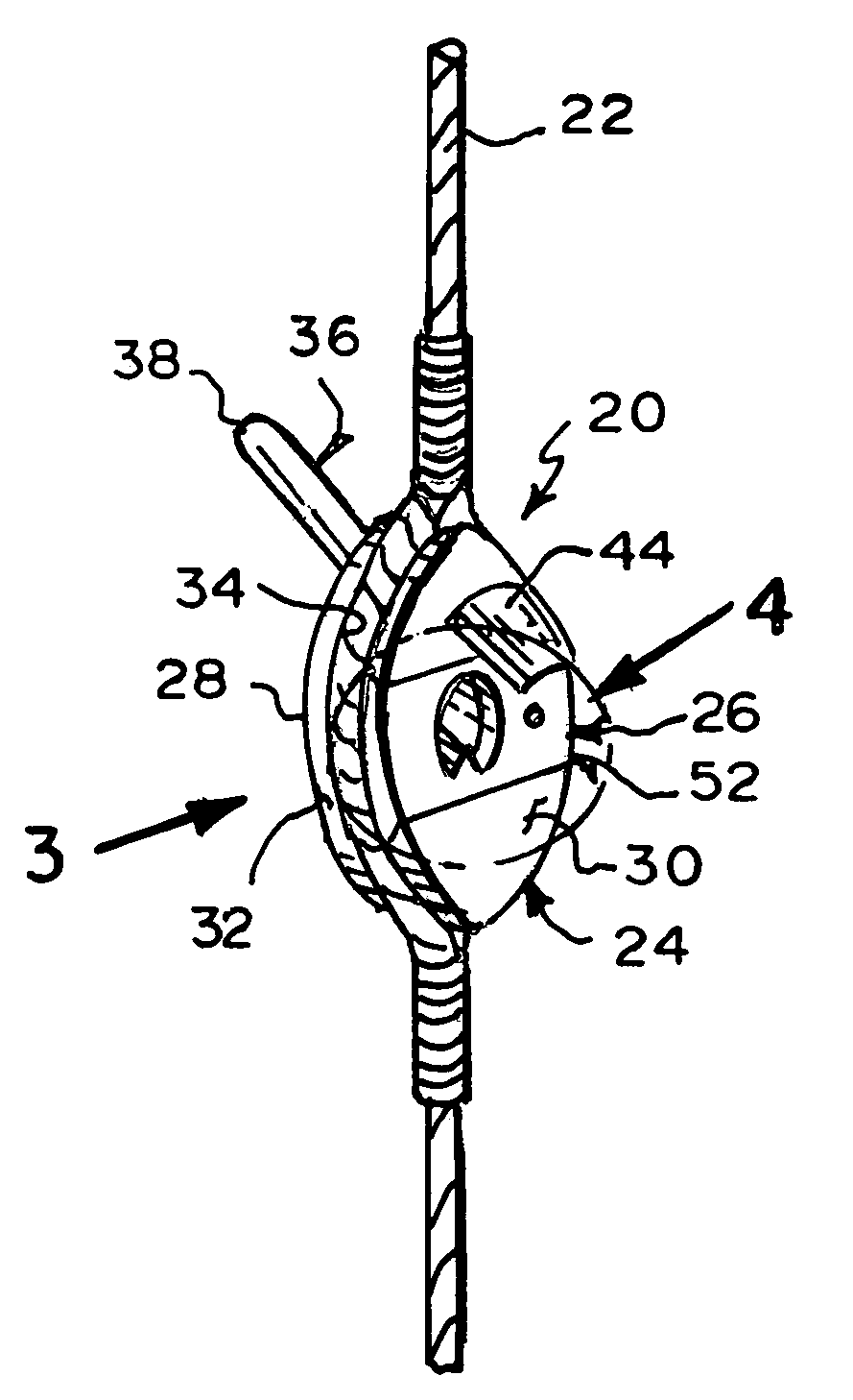
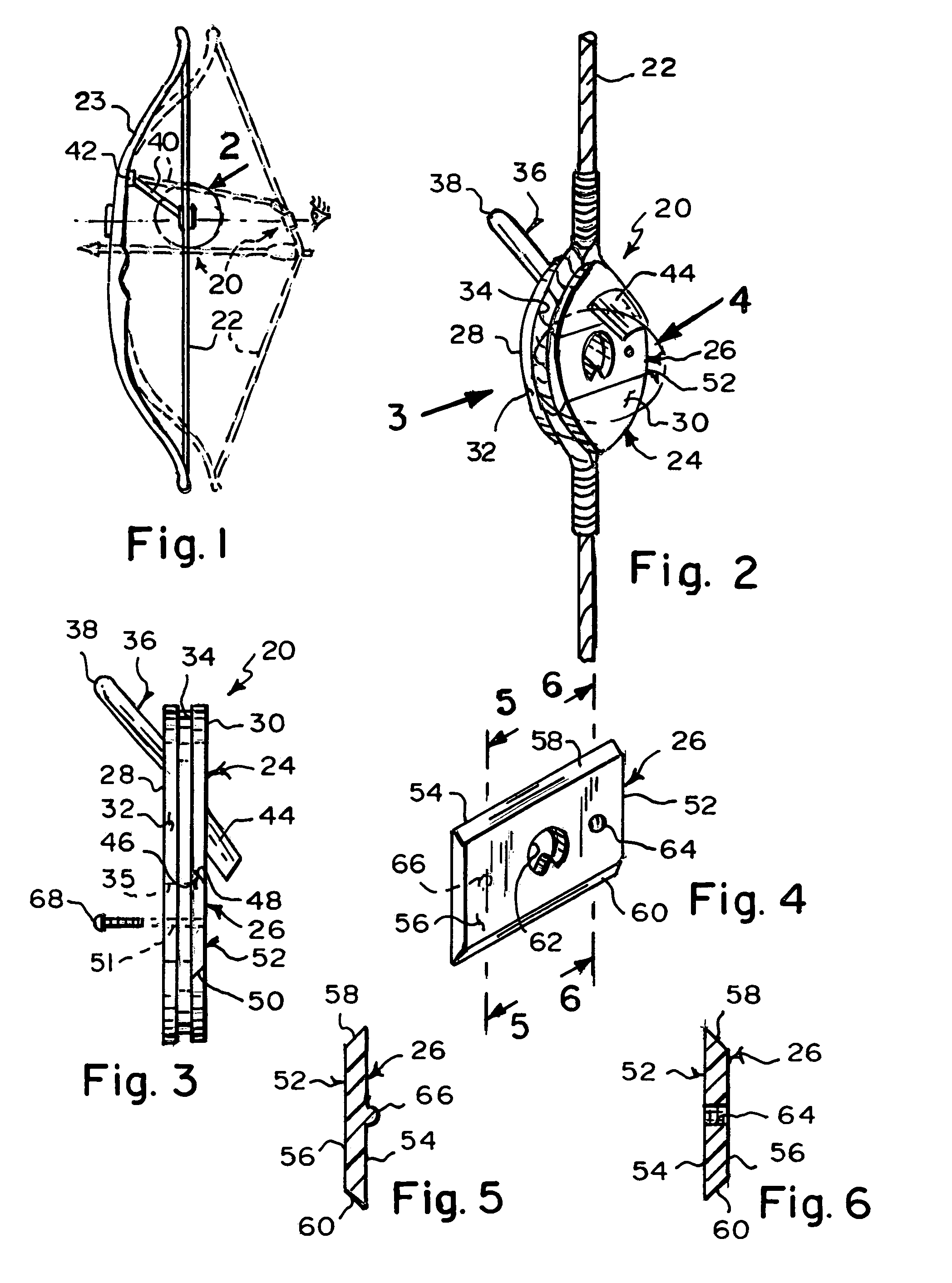
[0053]Referring now to the figures, in which like numerals indicate like parts, and particularly to FIG. 1, the rear peep sight of the present invention is shown generally at 20 for mounting to a string 22 of a bow 23 and having interchangeable sight ports for accommodating different user preferences.

[0054]The general configuration of the rear peep sight 20 can best be seen in FIGS. 2 and 3, and as such, will be discussed with reference thereto.

[0055]The rear peep sight 20 comprises a mounting member 24 and a sighting member 26. The mounting member 24 is for mounting to the string 22 of the bow 23 and the sighting member 26 is attached to the mounting member 24.

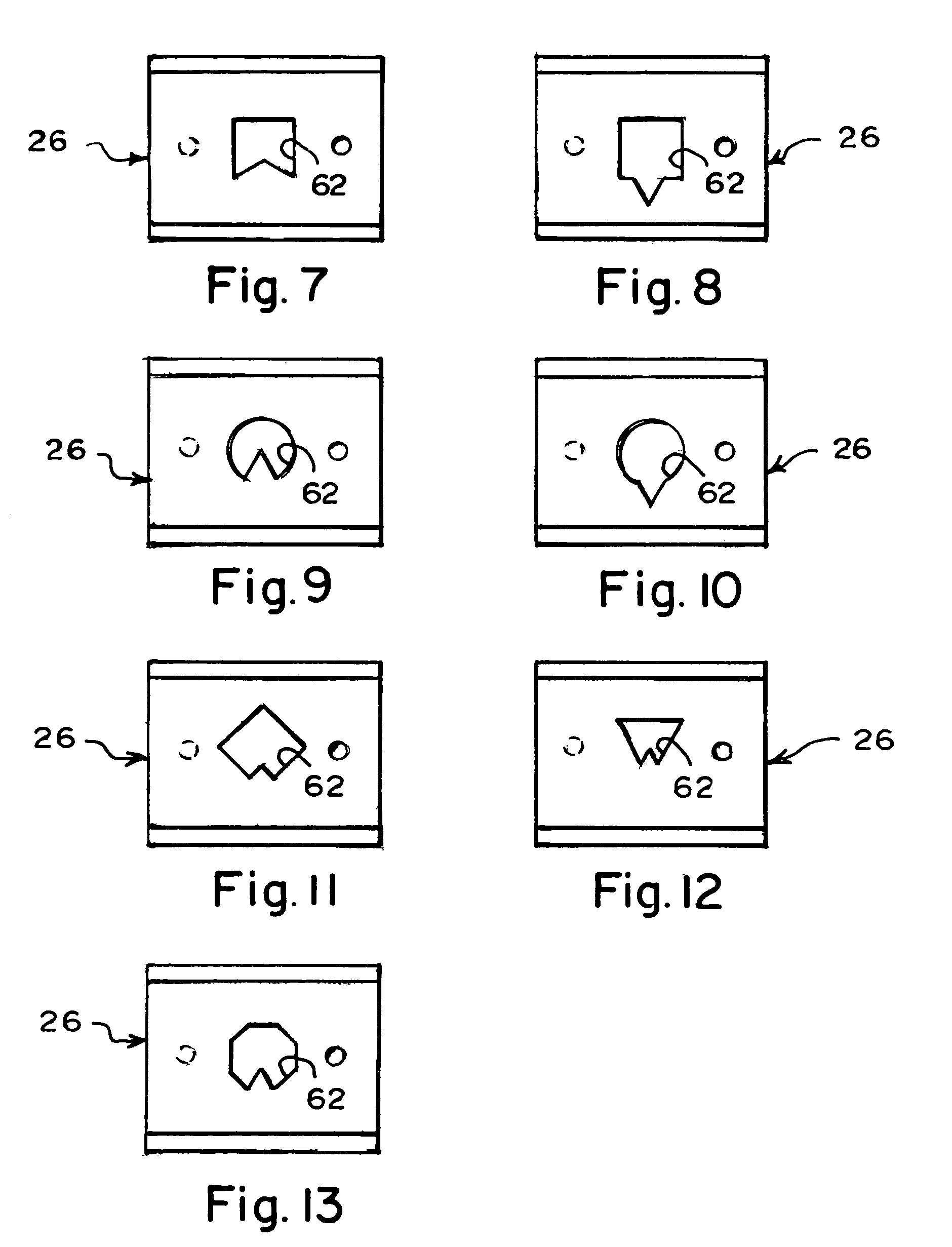
[0056]The sighting member 26 is interchangeably attached to the mounting member 24 so as to accommodate different user preferences of sight ports.

[0057]The specific configuration of the mounting member 24 can best be seen in FIGS. 2 and 3, and as such, will be discussed with reference thereto.

[0058]The mounting member 24 is g...


PUM


Abstract

A rear peep sight for mounting to a string of a bow and having interchangeable sight ports for accommodating different user preferences. A mounting member mounts to the string of the bow and a sighting member is interchangeably attached to the mounting member so as to accommodate different user preferences of sight ports. The mounting member has a channel that slidably receives the sighting member so as to provide a dove-tail joint that prevents the sighting member from vertical movement, yet allows for horizontal movement so as to allow the sighting member to slide sideways into the channel. The sighting member has an auxiliary through bore and a pimple that align with, and engage with, respectively, a pair of through bores in the mounting member. A screw extends freely through one through bore in the mounting member and threadably into the auxiliary through bore so as to maintain prevention of the sighting member from horizontal movement.

Description

BACKGROUND OF THE INVENTION[0001]1. Field of the Invention[0002]The present invention relates to a rear peep sight for mounting to a string of a bow. More particularly, the present invention relates to a rear peep sight for mounting to a bowstring and having interchangeable sight ports for accommodating different user preferences.[0003]2. Description of the Prior Art[0004]Numerous innovations for bow sights have been provided in the prior art that will be described. Even though these innovations may be suitable for the specific individual purposes to which they address, however, they differ from the present invention.[0005]A FIRST EXAMPLE, U.S. Pat. No. 3,410,644 to McLendon teaches telescopic sight means for a bow having an optical system comprising at least one optical lens sight means affixedlintegrally between the strands of the bowstring or mounted upon the bowstring, the lens preferably being sightingly aligned with a second optical lens sight affixed to the bow, whereby the t...

Claims


Application Information

Patent Timeline
Patent Type & Authority Patents(United States)
IPC IPC(8): F41B5/00
CPCF41G1/467F41B5/1419
Inventor SHAFFER, ALFRED H.SHAFFER, RICHARD D.
Owner SHAFFER ALFRED H
Learn More