Remote Control Method and System, Vehicle with Remote Controllable Function, and Control Server

a remote control and function technology, applied in the field of remote control techniques and vehicles with remote controllable functions, can solve problems such as undesirable operation of vehicle equipmen

Active Publication Date: 2008-10-30
TOYOTA JIDOSHA KK
View PDF74 Cites 71 Cited by
  • Summary
  • Abstract
  • Description
  • Claims
  • Application Information

AI Technical Summary

Benefits of technology

[0018]With the above-described arrangements, remote-control operations are appropriately ex

Problems solved by technology

Some problems arise from this arrangement.
If, in such situations, a driving signal is transmitted from the center in response to every activation request, vehicle equipment may be operated in an undesirable manner contrary to the intention of a person who is actually using the equipme

Method used


Image

  • Remote Control Method and System, Vehicle with Remote Controllable Function, and Control Server
  • Remote Control Method and System, Vehicle with Remote Controllable Function, and Control Server
  • Remote Control Method and System, Vehicle with Remote Controllable Function, and Control Server

Examples


first embodiment

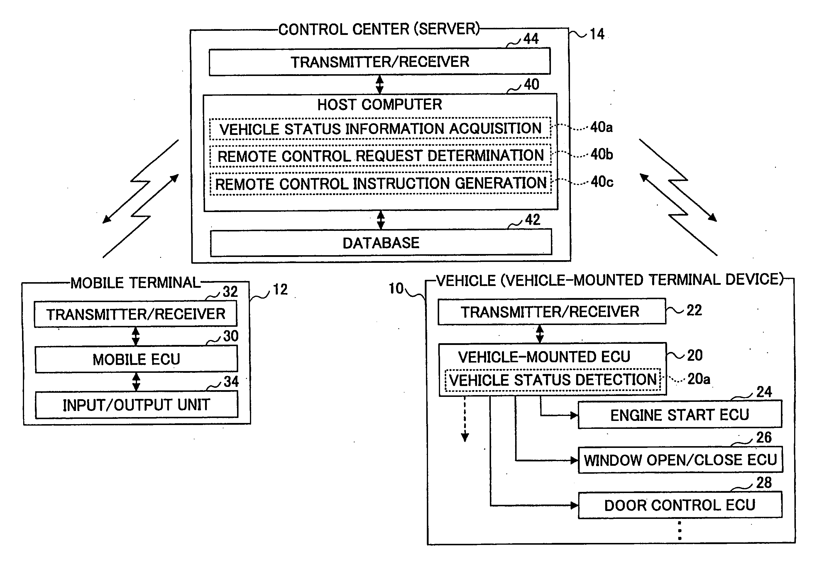
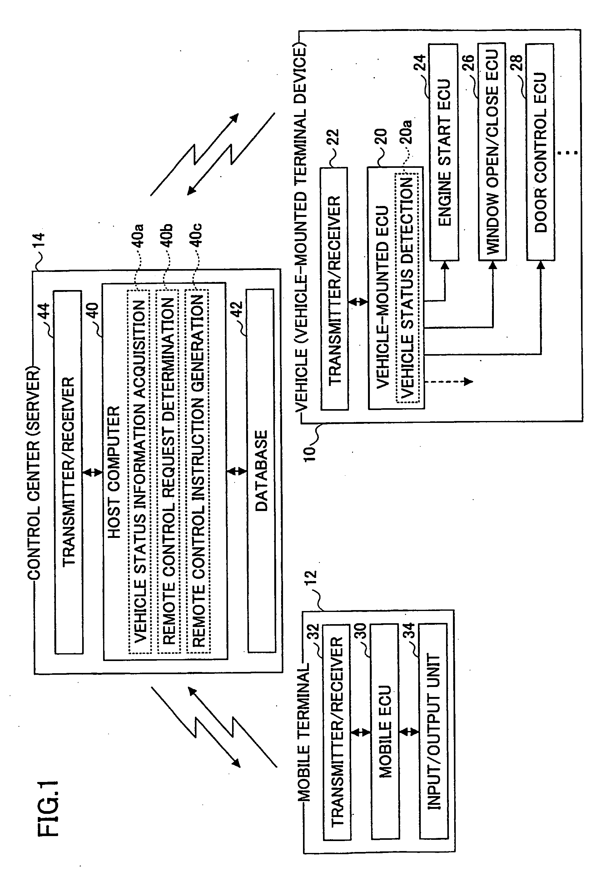
[0028]FIG. 1 is a schematic block diagram of a remote control system according to the first embodiment of the invention. The remote control system includes a terminal device 10 mounted in a vehicle (referred to as a “vehicle-mounted terminal device”), a mobile terminal 12 (e.g., a cellular phone, a personal computer, or a PDA) carried by an authorized user of the vehicle (such as a driver or an owner of the vehicle) and functioning as a remote controller, and a control center or server 14 (hereinafter simply referred to as “center 14”) that manages information needed for remote-control operations between the mobile terminal 12 and the vehicle-mounted terminal device 10. With the remote control system, equipment furnished in the vehicle (referred to as “vehicle equipment”) is operated or activated remotely via the center 14 based on manipulation of the mobile terminal 12. One or more mobile terminals 12 may be used for a vehicle.

[0029]The vehicle-mounted terminal device 10 has a vehi...

second embodiment

[0062]In the second embodiment, acceptability of a remote control request is determined at the vehicle-mounted terminal device 10, instead of at center 14, based on the detected vehicle status information (including local operation information and prior remote control result information). In this case, the vehicle-mounted ECU 20 performs a routine shown in FIG. 4.

[0063]FIG. 4 is a flowchart of a control routine executed by the vehicle-mounted ECU 20 of the vehicle-mounted terminal device 10 according to the second-embodiment. When the center 14 receives a remote control request for activating certain vehicle equipment from the mobile terminal 12, the center transmits a remote control instruction to the vehicle-mounted terminal device 10, and the vehicle-mounted terminal device 10 receives the remote control instruction from the center 14 via a wireless communication network (step 200). The center 14 functions as a gateway that transfers the remote control request from the mobile ter...

third embodiment

[0076]In the first and second embodiments, determination as to acceptability of currently requested remote-control operation is made at a single site, that is, at center 14, vehicle-mounted terminal device 10, or mobile terminal 12, based on local operation information and prior remote control results of other competitive remote control requests. In the third embodiment, determination as to acceptability of a current remote control request based on presence or absence of other competitive remote control requests is performed at the center 14, while remote control acceptability determination based on local operation information is performed at the vehicle-mounted terminal device 10.

[0077]FIG. 6 is a flowchart showing a control routine executed in a remote control system according to the third embodiment of the invention. Upon receiving a remote control request with respect to certain vehicle equipment from the mobile terminal 12 (step 300), the center 14 determines whether there is a...


PUM


Abstract

A remote control method for remotely controlling the operation of equipment furnished in a vehicle in response to a remote control request generated by a remote controller is provided. The method comprises the steps of (a) acquiring vehicle status information from the vehicle; (b) determining whether to operate particular vehicle equipment designated by the remote control request based on the vehicle status information; and (c) regulating the remote control request based on the determination result representing acceptability of remote-control operation of the requested vehicle equipment.

Description

BACKGROUND OF THE INVENTION[0001]The present invention generally relates to a remote control technique and a vehicle with a remote-controllable function, and more particularly, to a technique for operating vehicle equipment remotely in response to a request from a handy or mobile terminal device manipulated by a user of the vehicle.[0002]Conventionally, a remote control system, which includes a control center, a vehicle with prescribed equipment (e.g., power door lock / unlock), and a mobile terminal to be manipulated by a user of the vehicle, is known. See, for example, JP-A 2003-41821. In this system, when a request for activating vehicle equipment is input to the mobile terminal by the user of the vehicle, a request signal is transmitted to the control center. Upon receiving the request signal, the center transmits a driving signal to the vehicle to activate the vehicle equipment provided that a prescribed condition is satisfied. Then the driving signal causes the vehicle equipment...

Claims


Application Information

Patent Timeline
IPC IPC(8): G06F7/04B60R25/01B60R25/04B60R25/10B60R25/24E05B49/00H04Q9/00
CPCB60R25/2009B60R25/2018B60R2325/205G07C5/008
Inventor TAKI, NAOKIWATANABE, ATSUSHIOTSUKA, MAYUMI
Owner TOYOTA JIDOSHA KK
Why Eureka
Try Eureka