Braking control device for vehicle

a technology for brake control and vehicle, which is applied in the direction of braking systems, instruments, analogue processes for specific applications, etc., can solve the problems of vibration (judder) of the vehicle body or brake squeal, and achieve the effect of eliminating the complication of control, stable control of the electric motor, and operation speed of the braking operation member

US20150151727A1Active Publication Date: 2015-06-04ADVICS CO LTD
2 Cites 13 Cited by

Patent Information

Authority / Receiving Office
US · United States
Current Assignee / Owner
Publication Date
2015-06-04

Smart Images

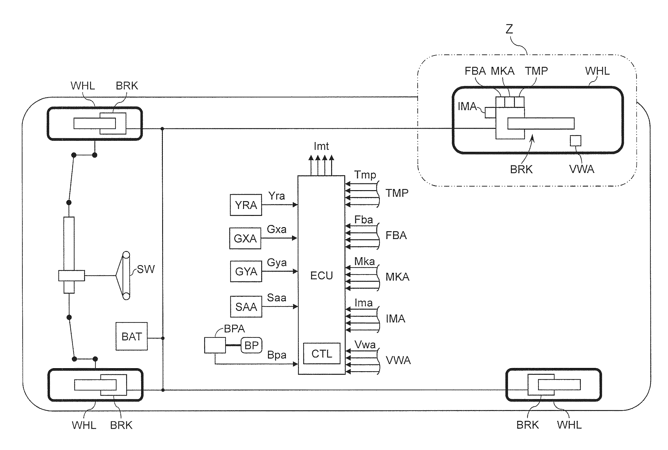
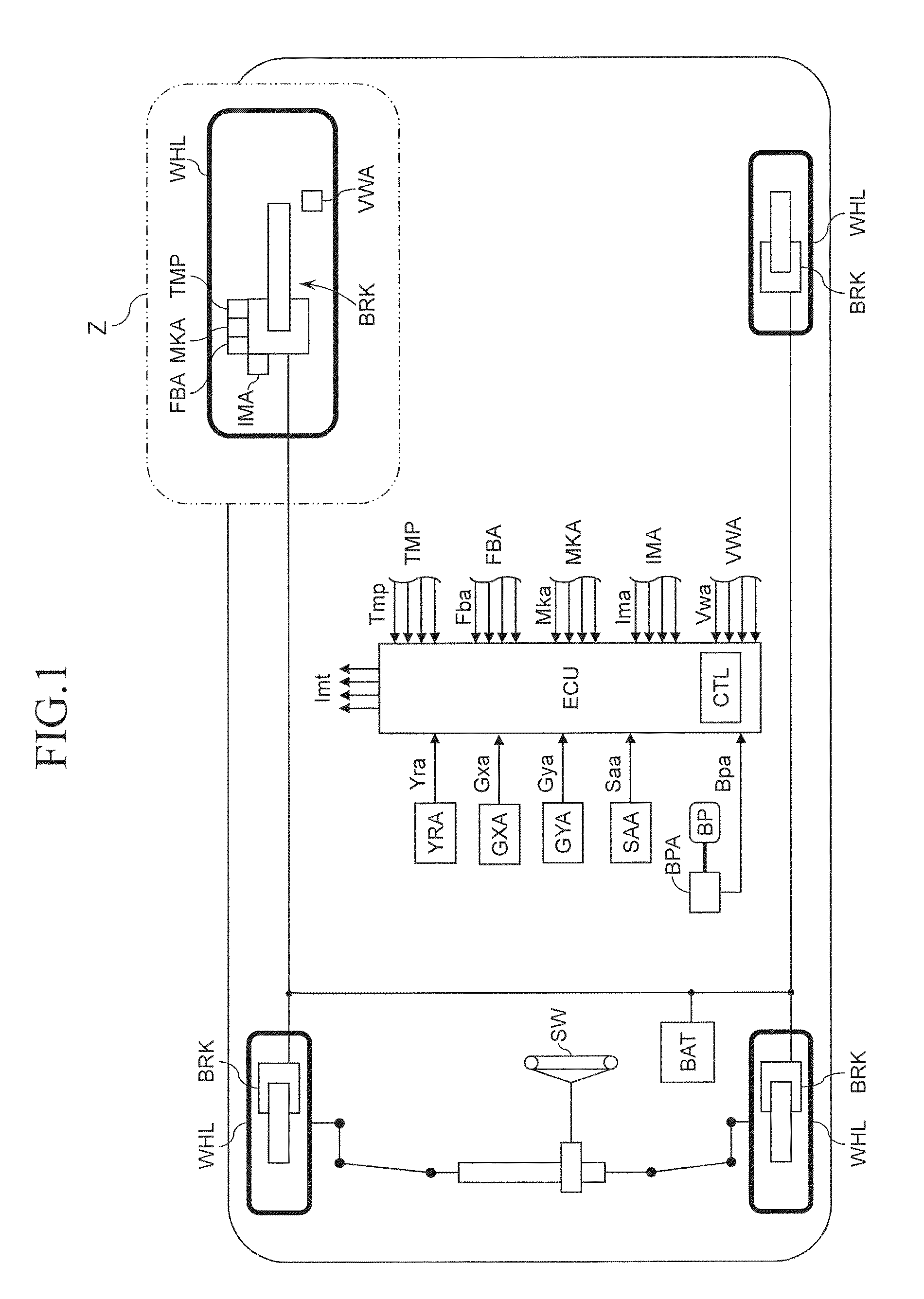
  • Figure 1
    Figure 1
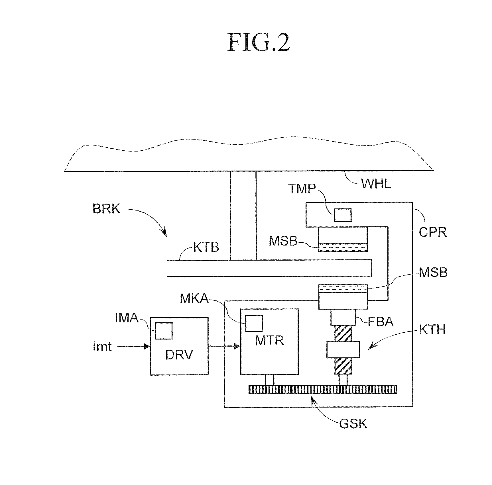
  • Figure 2
    Figure 2
  • Figure 3
    Figure 3
Patent Text Reader

Abstract

Based on a difference between target and actual values of a friction member force pressing a brake disc, feedback control over the pressing force is executed. As the actual value, a “limit pressing force (Fbs) obtained by placing a limitation on a temporal change amount of the Fba based on a limit value (Lmt)” is used. The limit value (Lmt) is set based on an electric motor speed (dMkt, dMka), a wheel speed (Vwa), and a temporal change amount (ΔTmp) of the friction member temperature. The Lmt is set to increase as the dMkt (dMka) increases and the temporal change amount (ΔTmp) of the temperature increases, and to also increase as the wheel speed (Vwa) decreases. Thus, even when a rotating member (brake disc) is deformed, braking torque control can be appropriately executed without accelerating a fluctuation of a braking torque on the wheel.
Need to check novelty before this filing date? Find Prior Art

Description

TECHNICAL FIELD

[0001] The present invention relates to a vehicle brake control device.BACKGROUND ART

[0002] Hitherto, there has been known a vehicle brake control device configured to generate a braking torque by an electric motor. In this type of device, typically, an indicator current (target current) is calculated based on an operation amount of a braking operation member for the vehicle by a driver, and the electric motor is controlled based on the indicator current. Then, a braking torque that depends on the operation of the braking operation member is applied to the wheels.

[0003] Regarding this type of device, Japanese Patent Application Laid-open No. 2000-283193 has the following description. Specifically, a thickness variation sometimes occurs in a sliding surface of a disc rotor due to frictional heat generated during braking or the like. In particular, when a braking-torque fluctuation occurs due to the thickness variation at the time of braking, a vibration (judder) of a vehi...

Examples

Embodiment Construction

[0030]Now, a vehicle brake control device according to embodiment of the present invention is described with reference to the drawings.

[0031]

[0032]As illustrated in FIG. 1, this vehicle is equipped with a braking operation member (for example, brake pedal) BP that is used by a driver for decelerating the vehicle, braking means (brake actuator) BRK by which a braking torque of each wheel is adjusted to generate a braking force therefor, an electronic control unit ECU for controlling the BRK, and a battery BAT as a power source for supplying electric power to the BRK, the ECU, and the like.

[0033]In addition, this vehicle includes braking operation amount acquisition means (for example, stroke sensor or leg-force sensor) BPA for detecting an operation amount Bpa of the BP, steering angle detection means SAA for detecting a steering angle Saa of a steering wheel SW operated by the driver, yaw rate detection means YRA for detecting a yaw rate Yra of the vehicle, longitudinal acceleration...