Water circulation system valve assemblies having water temperature control

a technology of water circulation system and valve assembly, which is applied in the direction of valve operating means/release devices, instruments, process and machine control, etc., can solve the problems of no method of “draining” and hot water not always readily available at the hot water side of the fixtur

Active Publication Date: 2009-01-08
GRUNDFOS PUMPS
View PDF33 Cites 52 Cited by
  • Summary
  • Abstract
  • Description
  • Claims
  • Application Information

AI Technical Summary

Problems solved by technology

A problem with most home and industrial water distribution systems is that hot water is not always readily available at the hot water side of the fixture when it is desired.
This problem is particularly acute in water use fixtures that are located a distance from the hot water heater or in systems with poorly insulated pipes.
As a result, the temperature of the water between the hot water heater and the fixture lowers until it becomes cold or at least tepid.
For certain fixtures, such as virtually all dishwashers and washing machines (which are not usually provided with a bypass valve), there typically is no method of “draining” away the cold or tepid water in the hot water pipes prior to utilizing the water in the fixture.
The inability to have hot water at the hot water side of the fixture when it is desired creates a number of problems.
One problem is having to utilize cold or tepid water when hot water is desired.
This is a particular problem for the dishwasher and washing machine fixtures in that hot water is often desired for improved operation of those appliances.
Even in those fixtures where the person can let the cold or tepid water flow out of the fixture until it reaches the desired warm or hot temperature, there are certain problems associated with such a solution.
One such problem is the waste of water that flows out of the fixture through the drain and, typically, to the sewage system.
This good and clean water is wasted (resulting in unnecessary water treatment after flowing through the sewage system).
Yet another problem associated with the inability to have hot water at the hot water valve when needed is the waste of time for the person who must wait for the water to reach the desired temperature.
However, these water recirculation systems have problems and limitations.
Problems arise when hot water is desired at the fixture before the end of a cycle, or when the pump is not running.
However, constantly running the pump so that hot water is always available is not economical.
Accordingly, the above mentioned problems (e.g. waste of water) are still prevalent in water recirculation systems today.
An additional problem with known bypass valves is that over time and with age the valves, particularly valves that are directly operated by a thermal actuator (such as a wax filled cartridge) tend not to have any toggle action.
While this meets the function of keeping the water at a remote fixture hot, leaving the valve in a slightly open condition does present two problems.
First, the lack of toggle action can result in scale build-up on the actuator body and / or rod because the rod is constantly extended.
However, these screens tend to clog themselves, limiting the flow to the bypass passage.
Second, the open valve constantly bleeds a small amount of hot or almost hot water into the cold water piping, thereby keeping the faucet end of the cold water pipe substantially warm.
It is also detrimental to have any noticeable crossover flow (siphoning) from hot to cold or cold to hot with any combination of faucet positions, water temperatures, or pump operation.

Method used


Image

  • Water circulation system valve assemblies having water temperature control
  • Water circulation system valve assemblies having water temperature control
  • Water circulation system valve assemblies having water temperature control

Examples


Embodiment Construction

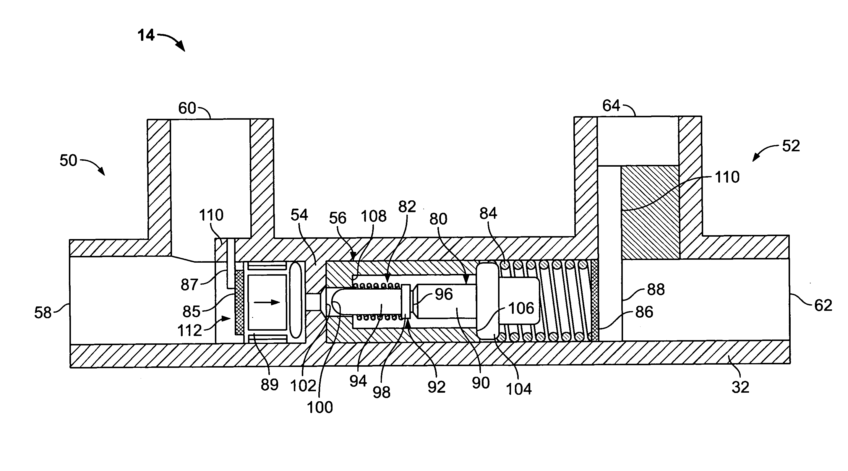
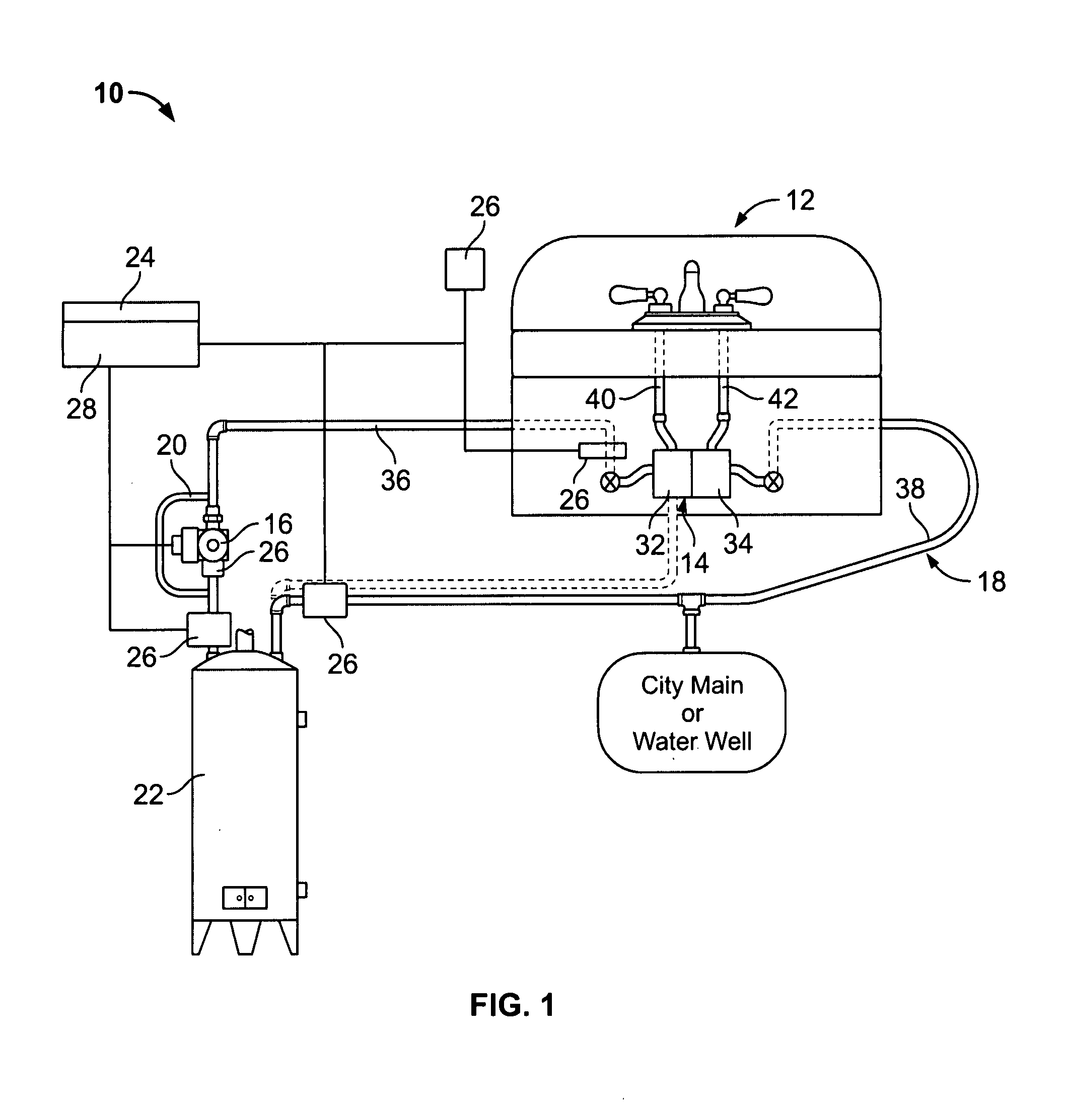
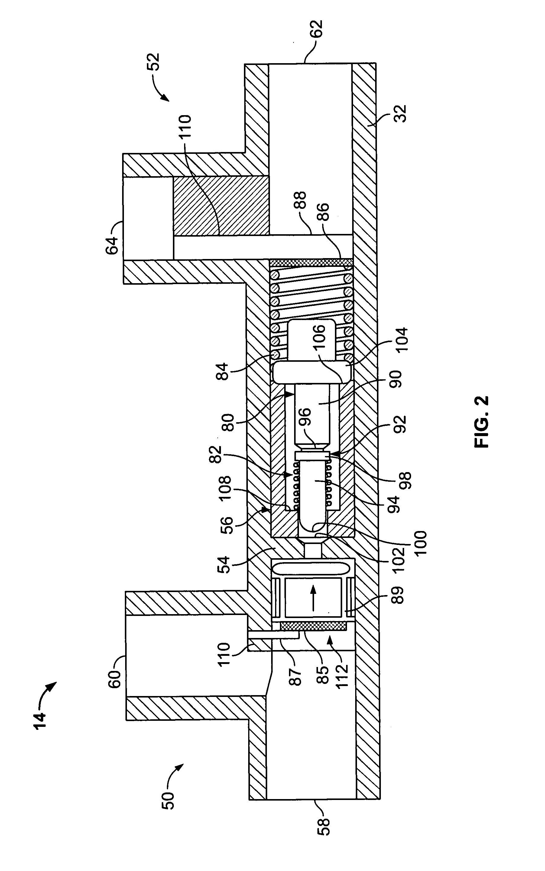
[0014]FIG. 1 is a side elevation view showing a water circulation system 10 and fixture 12 utilizing a valve assembly 14 in accordance with an exemplary embodiment. In order to achieve the desired circulation flow, a single circulating pump 16 is utilized as part of a piping system 18 of the water circulating system 10. The pump 16 may be a single, small pump of the type used in residential hot water space heating. To avoid reduced flow, a check valve 20 can be plumbed in parallel with the pump 16 or incorporated within the pump housing, to pass a flow rate exceeding the pump's capacity around the pump 16. When the pump 16 is powered and flow demand is low, the check valve 20 prevents the boosted flow from re-circulating back to its own inlet.

[0015]In the illustrated embodiment, the pump 16 is located at or near a water heater 22 in the discharge piping or hot water piping. While a conventional home water heater is illustrated in FIG. 1, it is realized that other types of water heat...


PUM


Abstract

A valve assembly for a water circulation system includes a valve body defining a bypass passage between a hot water side and a cold water side of the valve body. The bypass passage has a valve seat therein. A bypass valve is received within the bypass passage. The bypass valve restricts the flow of water through the bypass passage based on a temperature of the water in the bypass passage. The bypass valve is variably positionable with respect to the valve seat to control a bypass shut-off temperature of the water.

Description

BACKGROUND OF THE INVENTION[0001]The present invention relates generally to water circulating systems, and more particularly, to valve assemblies for water circulating systems.[0002]Home and industrial water distribution systems distribute water to various fixtures, including sinks, bathtubs, showers, dishwashers and washing machines, that are located throughout the house or industrial building. The typical water distribution system brings water in from an external source, such as a city main water line or a private water well, to the internal water distribution piping system. The water from the external source is typically either at a cold or cool temperature. One segment of the piping system takes this incoming cold water and distributes it to the various cold water connections located at the fixtures where it will be used (e.g., the cold water side of the faucet at the kitchen sink). Another segment of the piping system delivers the incoming cold water to a water heater which hea...

Claims


Application Information

Patent Timeline
Patent Type & Authority Applications(United States)
IPC IPC(8): F16K31/70F16K31/64
CPCF16K31/002G05D23/02G05D23/134Y10T137/7737Y10T137/7758Y10T137/6497Y10T137/2574
Inventor LUM, KENKEMPF, DALE
Owner GRUNDFOS PUMPS
Why Eureka
Try Eureka