

Liquid crystal display device
a display device and liquid crystal technology, applied in non-linear optics, instruments, optics, etc., can solve the problems of reducing the utilization efficiency and transmittance of light, increasing the power consumption of the backlight unit, and preventing the achievement of sufficient display luminance, etc., to achieve high light utilization efficiency
- Summary
- Abstract
- Description
- Claims
- Application Information
AI Technical Summary
Benefits of technology
Problems solved by technology
Method used
Image

Examples
first embodiment
[0062]With reference to the drawings, a detailed description will be given of a liquid crystal display device according to the present invention.
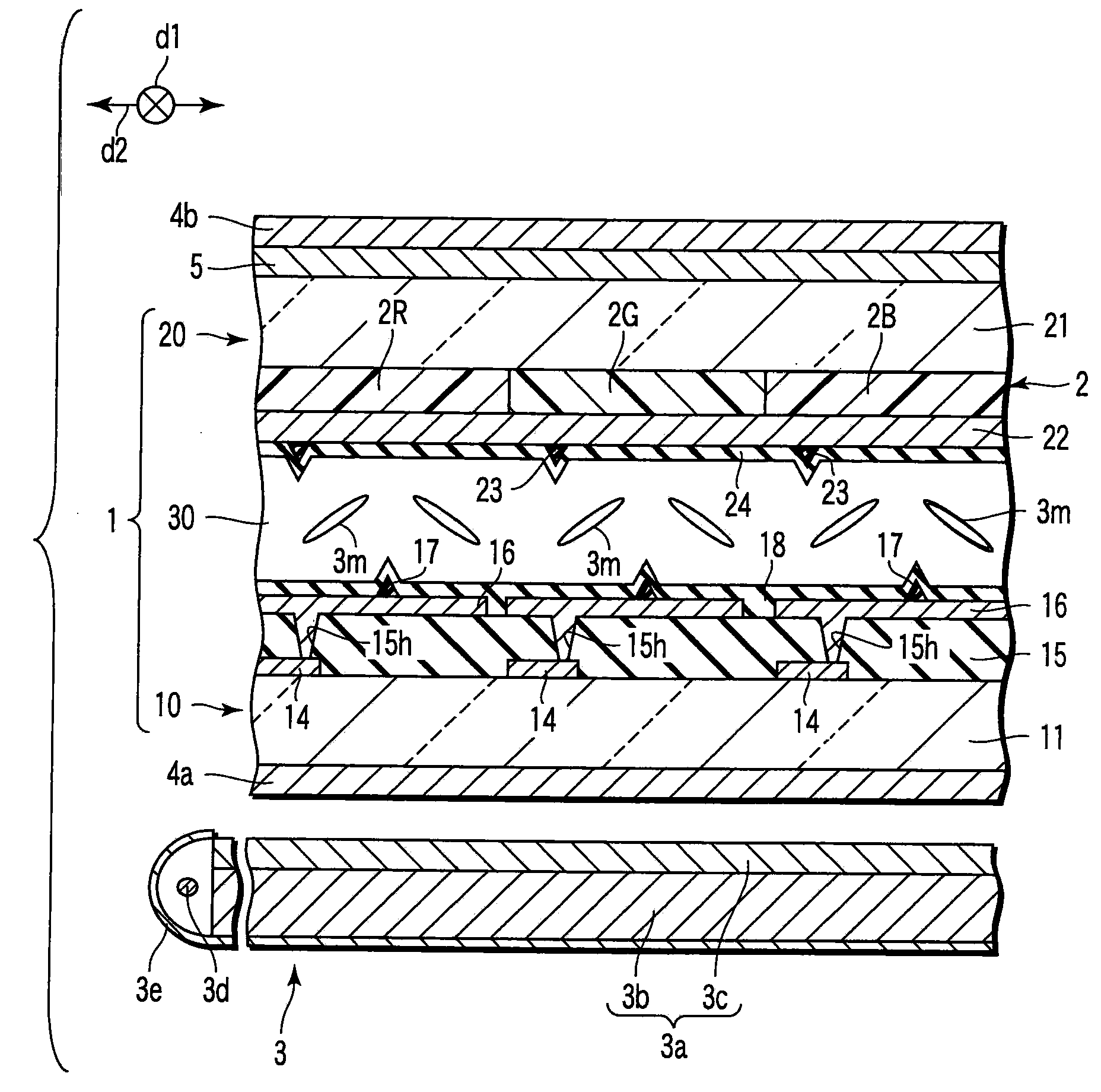
[0063]As shown in FIGS. 1 to 4, the liquid crystal display device comprises a liquid crystal display panel 1, a color filter 2, a backlight unit 3, a polarizing plate 4a, a polarizing plate 4b, a polarizing reflection layer 5, and a control section 9.
[0064]The liquid crystal display panel 1 comprises an array substrate 10, an opposite substrate 20 arranged opposite to the array substrate 10 with a predetermined gap between the array substrate 10 and the opposite substrate 20, and a liquid crystal layer 30 held between the array substrate and the opposite substrate. The liquid crystal display panel 1 comprises a rectangular display area R.
[0065]The array substrate 10 as a first substrate has a rectangular glass substrate 11. The opposite substrate 20 as a second substrate has a rectangular glass substrate 21. The glass substrates 11 and 21 a...
embodiment 1
[0123]The present inventor has examined the optical characteristics of the liquid crystal display device according to the variation. The results of the examination indicate that the liquid crystal display device according to the variation offers optical characteristics equivalent to or more excellent than those of the liquid crystal display device , that is, optical characteristics exhibiting values equivalent to or greater than those shown in FIG. 9.
[0124]Now, description will be given of the effects of the provision of the color filter 2 between the polarizing plate 4b and the polarizing reflection layer 5, together with conventional problems.
[0125]First, if the color filter 2 is provided between the polarizer and the photodetector, the polarized light having entered the color filter is disrupted to some degree by the color filter. The contact characteristic is thus degraded. A pigment is dispersed in the color filter 2. The polarized light disruption phenomenon (hereinafter refer...
second embodiment
[0153]Now, description will be given of a liquid crystal display device according to the present invention.
[0154]As shown in FIG. 14, the liquid crystal display device comprises the liquid crystal display panel 1, the color filter 2, the backlight unit 3, the polarizing plate 4a, the polarizing plate 4b, the polarizing reflection layer 5, the control portion 9, and a polarizing reflection layer 7 as an another polarizing reflection layer.
[0155]In the present embodiment, each of the alignment films 18 and 24 is formed of a horizontal alignment film. Each of the alignment films 18 and 24 is formed using AL3456 (manufactured by JSR). The alignment film 18 is subjected to rubbing in the first direction d1. The alignment film 24 is subjected to rubbing in the second direction d2. The liquid crystal layer 30 exhibits dielectric constant anisotropy formed by a positive nematic liquid crystal. In the present embodiment, the liquid crystal layer 30 is formed using ZLI4792 (manufactured by Me...
PUM
 Abstract
Description
Claims
Application Information