Light projecting device having high light utilization efficiency

a technology of light projecting device and light beam, which is applied in the direction of lighting apparatus, vehicle components, lighting and heating apparatus, etc., can solve the problems of insufficient light intensity of low beam or high beam lights, and cannot meet the design requirements of miniaturization, and achieve the effect of high light utilization efficiency

Active Publication Date: 2020-06-11
CHIAN YIH OPTOTECH CO LTD
View PDF0 Cites 6 Cited by
  • Summary
  • Abstract
  • Description
  • Claims
  • Application Information

AI Technical Summary

Benefits of technology

[0007]In response to the above-referenced technical inadequacies, the present disc

Problems solved by technology

However, the optical designs of the light core structures cannot fully utilize lights of the LED lighting unit, and thus there is a concern that the light intensity of the low beam or hig

Method used


Image

  • Light projecting device having high light utilization efficiency
  • Light projecting device having high light utilization efficiency
  • Light projecting device having high light utilization efficiency

Examples


first embodiment

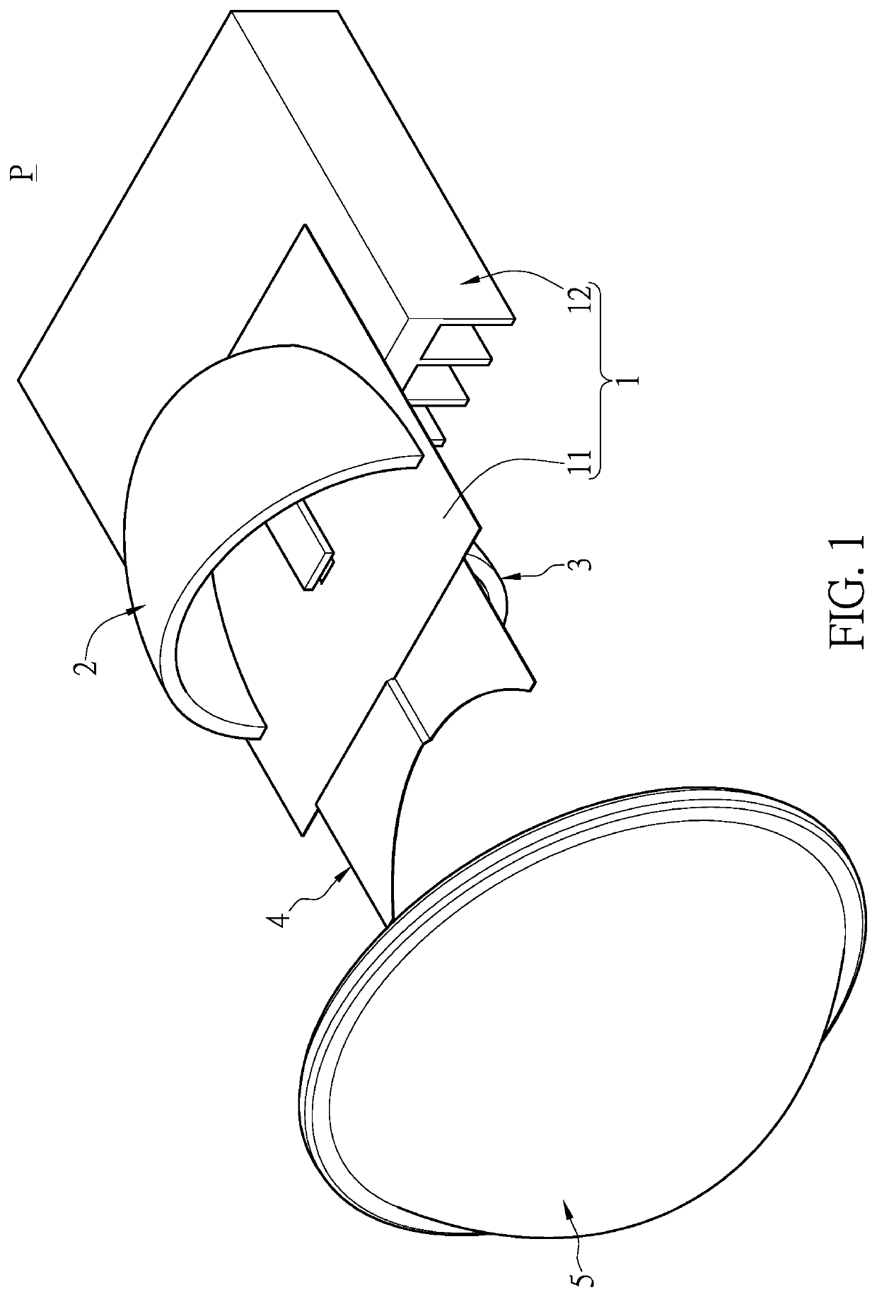
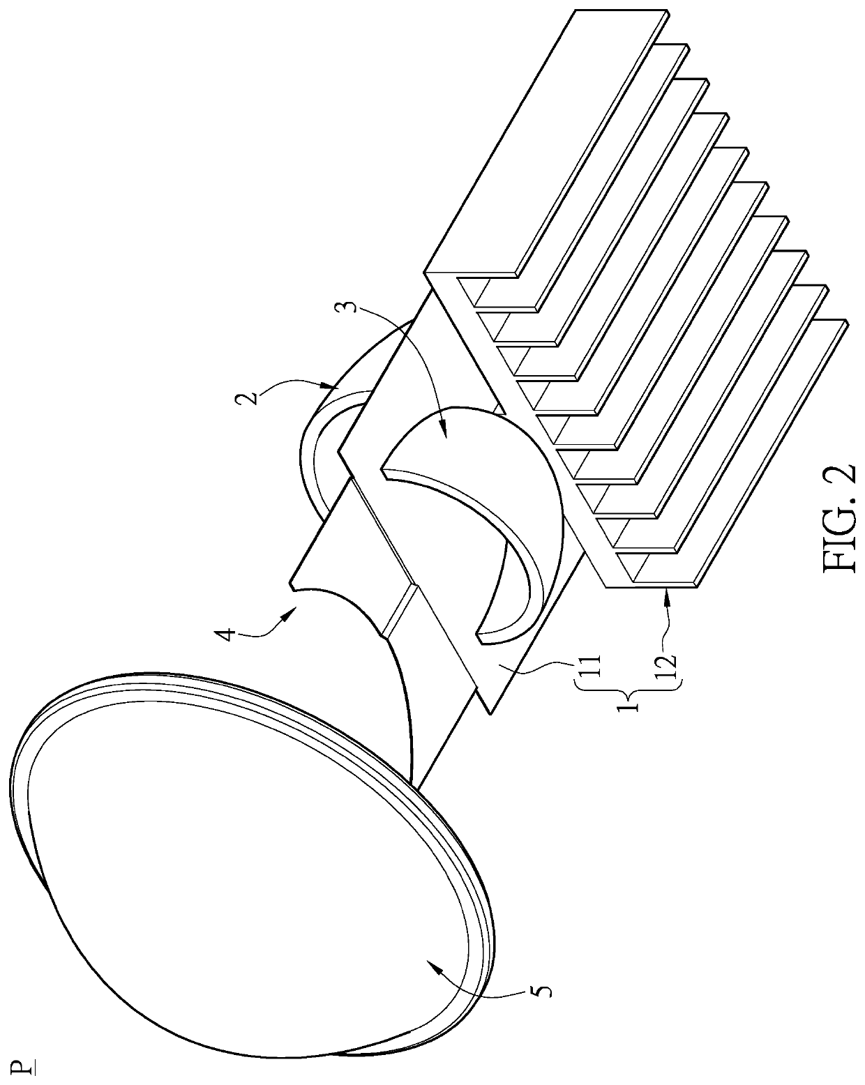
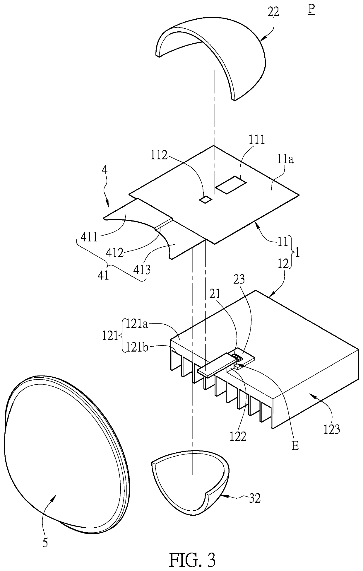
[0059]Referring to FIG. 1 to FIG. 7, the first embodiment of the present disclosure provides a light projecting device P which includes a supporting unit 1, a first light source 2, a second light source 3, a light guiding unit 4 and a lens 5. The first light source 2 and the second light source 3 both are disposed on the supporting unit 1. The first light source 2 includes at least one first lighting unit 21 and a first reflecting unit 22 corresponding in position to the at least one first lighting unit 21. The second light source 3 includes at least one second lighting unit 31 and a second reflecting unit 32 corresponding in position to the at least one second lighting unit 31. The light guiding unit 4 is disposed in front of the supporting unit 1 and the lens 5 is disposed in front of the light guiding unit 4. It is worth mentioning that, the first lighting unit 21 has a first light emitting surface 211 and the second lighting unit 31 has a second light emitting surface 311, and t...

second embodiment

[0075]Referring to FIG. 10 to FIG. 15, the second embodiment of the present disclosure provides a light projecting device P which includes a supporting unit 1, a first light source 2, a second light source 3, a light guiding unit 4 and a lens 5. The first light source 2 and the second light source 3 both are disposed on the supporting unit 1. The first light source 2 includes at least one first lighting unit 21 and a first reflecting unit 22 corresponding in position to the at least one first lighting unit 21. The second light source 3 includes at least one second lighting unit 31 and a second reflecting unit 32 corresponding in position to the at least one second lighting unit 31. The light guiding unit 4 is disposed in front of the supporting unit 1 and the lens 5 is disposed in front of the light guiding unit 4. It is worth mentioning that, the first lighting unit 21 has a first light emitting surface 211 and the second lighting unit 31 has a second light emitting surface 311, an...

third embodiment

[0082]Referring to FIG. 21 to FIG. 28, the third embodiment of the present disclosure provides a light projecting device P which includes a supporting unit 1, a first light source 2, a second light source 3, a light guiding unit 4 and a lens 5. The first light source 2 and the second light source 3 both are disposed on the supporting unit 1. The first light source 2 includes at least one first lighting unit 21 and a first reflecting unit 22 corresponding in position to the at least one first lighting unit 21. The second light source 3 includes at least one second lighting unit 31 and a second reflecting unit 32 corresponding in position to the at least one second lighting unit 31. The light guiding unit 4 is disposed in front of the supporting unit 1 and the lens 5 is disposed in front of the light guiding unit 4. It is worth mentioning that, the first lighting unit 21 has a first light emitting surface 211 and the second lighting unit 31 has a second light emitting surface 311, and...


PUM


Abstract

A light projecting device includes a supporting unit, a first light source, a second light source, a light guiding unit and a lens. The first light source and the second light source are disposed on the supporting unit. The first light source includes a first lighting unit having a first light emitting surface. The second light source includes a second lighting unit having a second light emitting surface. The light emitting direction of the first light emitting surface is opposite to that of the second light emitting surface, and the first light emitting surface is substantially coplanar with the second light emitting surface. The light guiding unit is disposed in front of the supporting unit and the lens is disposed in front of the light guiding unit. Therefore, the light utilization efficiency of the light projecting device can be increased while satisfying requirements for miniaturization.

Description

CROSS-REFERENCE TO RELATED PATENT APPLICATION[0001]This application claims the benefit of priority to Taiwan Patent Application No. 107143704 filed on Dec. 5, 2018. The entire content of the above identified application is incorporated herein by reference.[0002]Some references, which may include patents, patent applications and various publications, may be cited and discussed in the description of this disclosure. The citation and / or discussion of such references is provided merely to clarify the description of the present disclosure and is not an admission that any such reference is “prior art” to the disclosure described herein. All references cited and discussed in this specification are incorporated herein by reference in their entireties and to the same extent as if each reference was individually incorporated by reference.FIELD OF THE DISCLOSURE[0003]The present disclosure relates to a light projecting device, and more particularly to a light projecting device having high ligh...

Claims


Application Information

Patent Timeline
IPC IPC(8): F21S41/32F21S41/148F21S41/147F21S41/33F21V29/76F21S41/365F21S41/255F21S45/47
CPCF21S41/336F21S45/47F21S41/148F21S41/365F21S41/255F21S41/321F21W2102/135F21S41/147F21V29/763F21S41/151F21S41/192F21S41/24F21S41/295F21S41/39F21S41/43F21S41/47F21S41/663F21S45/49
Inventor WANG, CHENG
Owner CHIAN YIH OPTOTECH CO LTD
Why Eureka
Try Eureka