Two-dimensional image forming apparatus

Active Publication Date: 2006-10-12
PANASONIC CORP
View PDF6 Cites 34 Cited by
  • Summary
  • Abstract
  • Description
  • Claims
  • Application Information

AI Technical Summary

Benefits of technology

[0038] Therefore, it is possible to avoid occurrence of a high-order diffracted light which is scattered at a large angle that is caused by a difference in levels between adjacent conca

Problems solved by technology

By the way, in the conventional laser display, since the laser sources which output high-coherent light beams are used as light sources, so-called speckle noise might occur.
However, a mechanism

Method used


Image

  • Two-dimensional image forming apparatus
  • Two-dimensional image forming apparatus
  • Two-dimensional image forming apparatus

Examples


embodiment 1

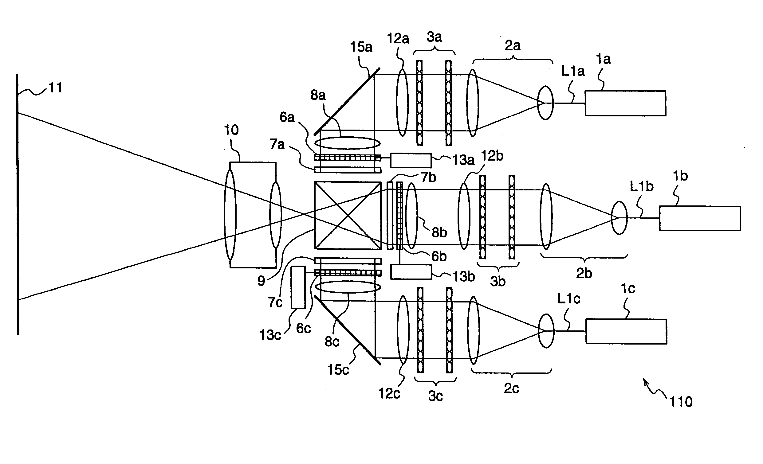
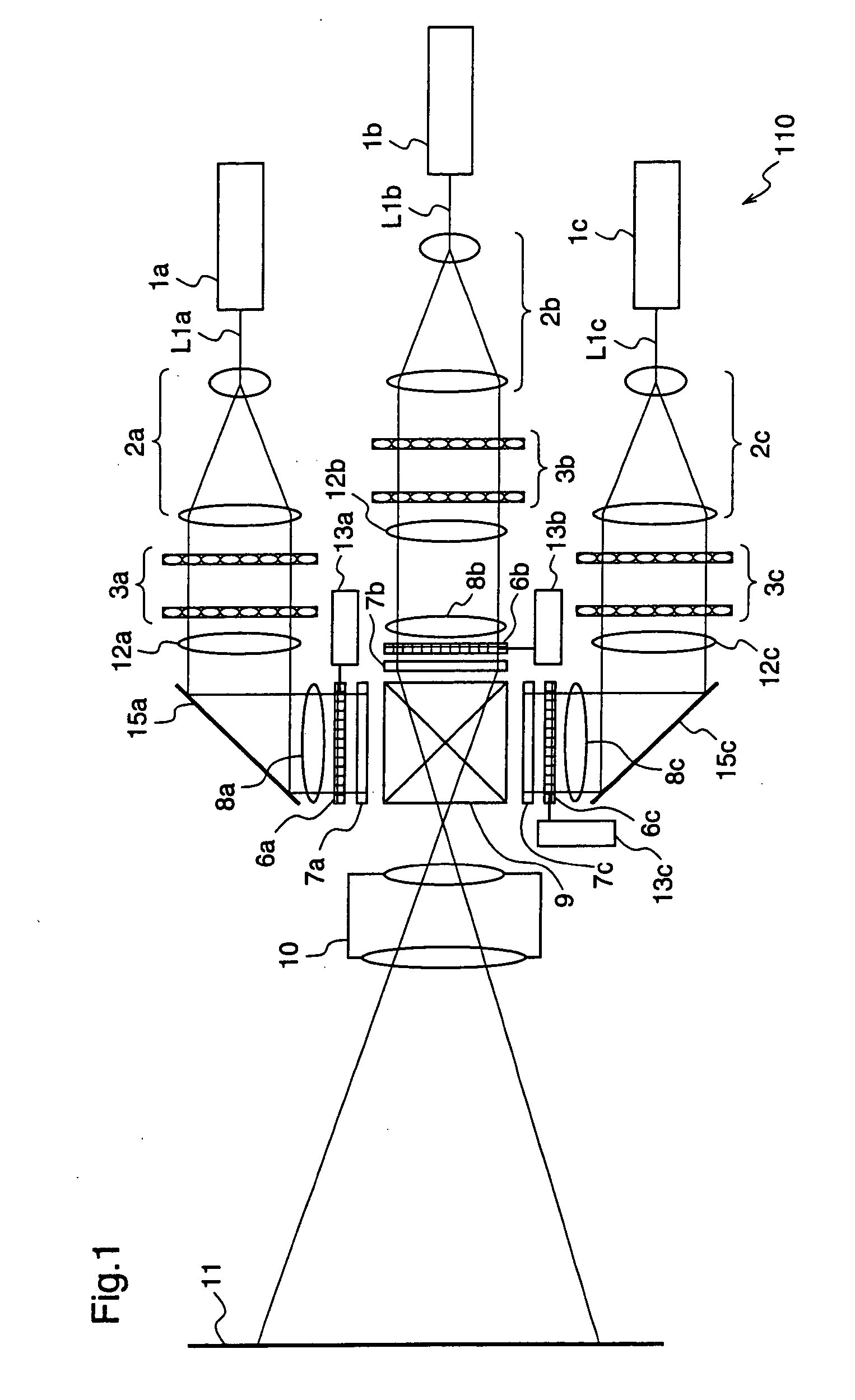
[0050]FIG. 1 is a schematic block diagram for explaining a two-dimensional image formation apparatus according to a first embodiment of the present invention.

[0051] The two-dimensional image formation apparatus 110 shown in FIG. 1 includes laser sources 1a˜1c as coherent light sources corresponding to primary color signals of RGB primary colors, diffusers 6a˜6c for diffusing light beams, and illumination optical systems for irradiating the diffusers 6a˜6c with laser beams L1a˜L1c outputted from the laser sources 1a˜1c, respectively. Further, the two-dimensional image formation apparatus 110 includes diffuser vibration units 13a˜13c for vibrating the respective diffusers 6a˜6c, spatial light modulators 7a˜7c for modulating the light beams that are emitted from the laser sources 1a˜1c and diffused by the diffusers 6a˜6c, which modulators 7a˜7c are constituted by liquid crystal panels or the like, a dichroic prism 9 for multiplexing the light beams that have passed through the spatial...

embodiment 2

[0088] FIGS. 4(a) and 4(b) are diagrams for explaining a two-dimensional image formation apparatus according to a second embodiment of the present invention. FIG. 4(a) shows a numerical aperture NAin of illumination light, and a numerical aperture NAout of an emitted light from the spatial light modulator 7a, and FIG. 4(b) shows a diffusion angle θ of the diffuser 6a. In the figures, the same or corresponding constituents as those shown in FIG. 3 are given the same reference numerals, and description thereof will be omitted.

[0089] An illumination optical system corresponding to the red laser source 1a of the two-dimensional image formation apparatus 120 according to the second embodiment has a rod type light integrator 14a and a projector lens 15a, instead of the light integrator 3a and the condenser lens 12a of the illumination optical system corresponding to the red laser source 1a of the two-dimensional image formation apparatus 110 according to the first embodiment.

[0090] The ...

embodiment 3

[0099]FIG. 5 is a diagram for explaining a two-dimensional image formation apparatus according to a third embodiment of the present invention, illustrating a diffuser as a constituent of the two-dimensional image formation apparatus.

[0100] This third embodiment is different from the first and second embodiments in that the third embodiment employs a pseudo random diffuser 18 having a regular concave-convex configuration at its surface while the first and second embodiments employ a frosted glass diffuser having a random concave-convex configuration at its surface.

[0101] The diffuser according to the first and second embodiments is usually fabricated by randomly roughening the surface of a transparent substrate such as glass or plastic. On the other hand, the pseudo random diffuser 18 according to the third embodiment is fabricated so as to form a concave-convex configuration at its surface, by partitioning the surface of a transparent substrate in a reticular pattern, and processi...


PUM


Abstract

A two-dimensional image formation apparatus according to the present invention is provided with laser sources (1a)˜(1c), diffusers (6a)˜(6c) for diffusing light, illumination optical systems for irradiating the diffusers (6a)˜(6c) with lights emitted from the laser sources (1a)˜(1c), diffuser vibration units (13a)˜(13c) for vibrating the diffusers (6a)˜(6c), and spatial light modulators (7a)˜(7c) disposed near the diffusers (6a)˜(6c), for modulating the lights emitted from the laser sources (1a)˜(1c) and diffused by the diffusers (6a)˜(6c), wherein the diffusers (6a)˜(6c) are vibrated by the diffuser vibration units (13a)˜(13c) at a velocity that satisfies a relationship, V>d×30 (millimeters/sec), which is established between the grain size d of the diffusers and the vibration speed V of the diffusers, whereby speckle noise existing in an image projected on a screen (11) can be effectively reduced.

Description

TECHNICAL FIELD [0001] The present invention relates to a two-dimensional image formation apparatus and, more particularly, to an image display apparatus such as a television receiver or a video projector, or an image formation apparatus such as a semiconductor exposure device. BACKGROUND ART [0002]FIG. 7 is a diagram illustrating the schematic structure of a conventional laser display. [0003] This laser display 100 includes laser sources 101a˜101c corresponding to RGB primary colors and light modulators 106a˜106c for subjecting laser beams La˜Lc outputted from the laser sources 101a˜101c to intensity modulation according to primary color signals Sa˜Sc of an input video signal. The laser display 100 further includes a mirror 103 for reflecting the laser beam La modulated by the light modulator 106a, a dichroic mirror 102a for multiplexing the laser beam Lb modulated by the light modulator 106b and the laser beam La reflected at the mirror 103, and a dichroic mirror 102b for multiple...

Claims


Application Information

Patent Timeline
IPC IPC(8): G03B21/26G02B5/02G02B27/14G02B27/48H04N9/31
CPCG02B5/0221G02B5/0278G02B27/1046G02B27/149H04N9/3197H04N9/3105H04N9/3152H04N9/3161G02B27/48G02B21/0056
Inventor KASAZUMI, KEN'ICHIMIZUUCHI, KIMINORIYAMAMOTO, KAZUHISA
Owner PANASONIC CORP
Why Eureka
Try Eureka