Light guide plate and surface light source device

a light guide plate and surface light source technology, which is applied in the direction of planar/plate-like light guides, lighting and heating apparatus, instruments, etc., can solve the problems of reducing the light use efficiency, and reducing the height of light sources such as leds, so as to reduce the leakage of light, improve the light use efficiency, and efficiently enter the light guide plate

Active Publication Date: 2015-10-15
ORMON CORP
View PDF6 Cites 35 Cited by
  • Summary
  • Abstract
  • Description
  • Claims
  • Application Information

AI Technical Summary

Benefits of technology

[0029]The light guide plate or the surface light source device according to one or more embodiments of the present invention includes the directivity changing unit at the end of the light guide plate, and enables light from a light source, which is arranged to face the end face of the directivity changing unit, to efficiently enter the light guide plate. The light entering the light guide plate is directed toward the light emitting surface after it is reflected by the inner inclined surfaces and the outer inclined surfaces. This reduces the leak of light. As a result, the surface light source device can be thinner and have higher light use efficiency.
[0030]The light incident on the light incident surface and entering the light guide plate is reflected on the inner inclined surfaces and widened in the lateral direction of the light guide plate (the width direction of the light guide plate member) to reduce the amount of light traveling in front of the light source. This controls the brightness of light emission in front of the light source on the light emitting surface, and achieves uniform brightness distribution on the light emitting surface.
[0031]The light widened laterally by the inner inclined surfaces is reflected on the outer inclined surfaces and bent in a direction parallel to the light incident surface. This prevents light from leaking out of the light guide plate from the sides of the light guide plate member or from the lenticular lens, and prevents the light use efficiency from being lowered.

Problems solved by technology

Although a light guide plate, which is a flat plate, can reduce its thickness, a light source such as an LED has a limitation in reducing its height.
This lowers the light use efficiency.
Such light loss would lower the light use efficiency and lower the uniformity of brightness.
This prevents light from leaking out of the light guide plate from the sides of the light guide plate member or from the lenticular lens, and prevents the light use efficiency from being lowered.

Method used


Image

  • Light guide plate and surface light source device
  • Light guide plate and surface light source device
  • Light guide plate and surface light source device

Examples


first embodiment

Modification of First Embodiment

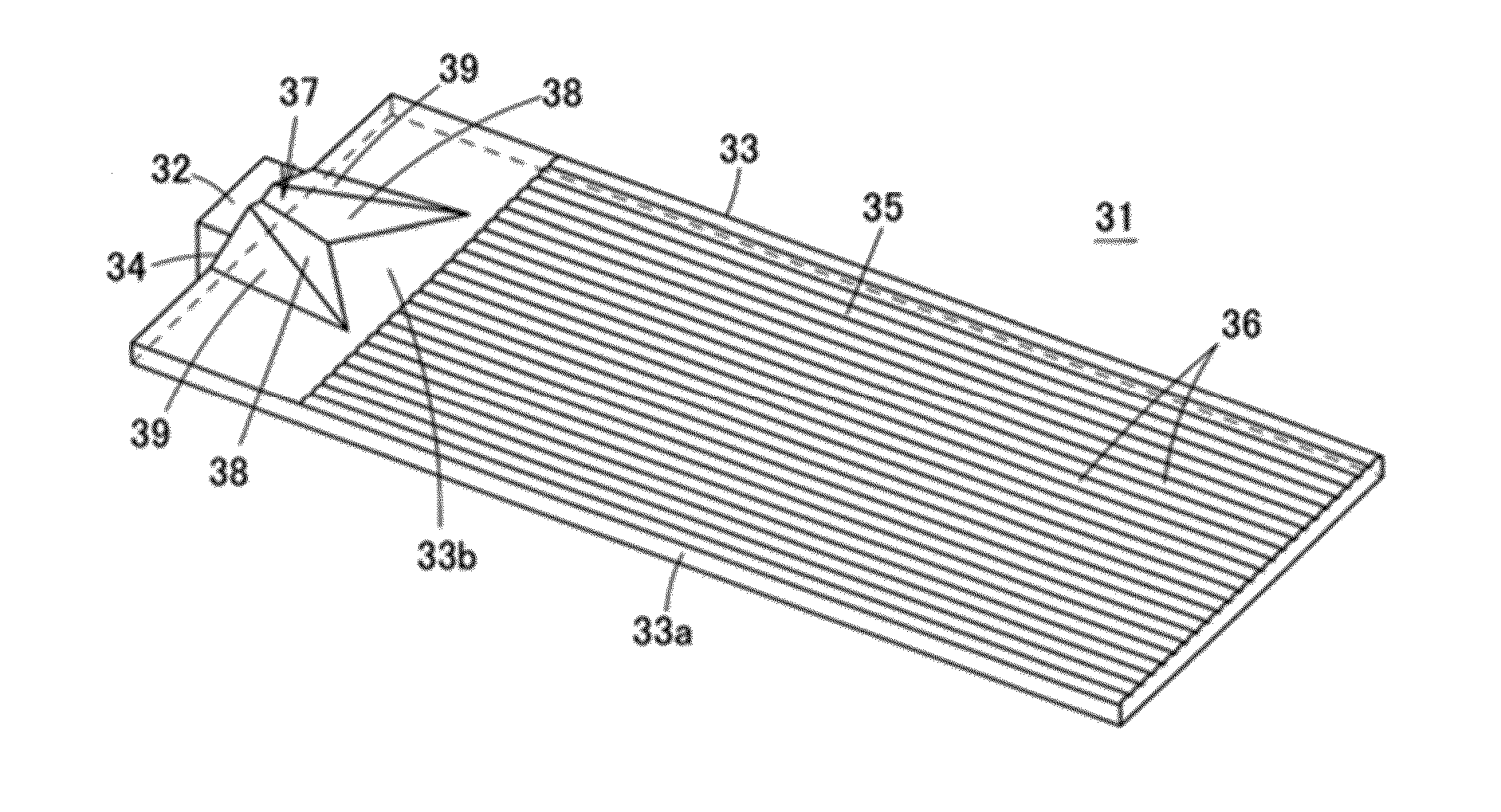
[0069]FIG. 9 is a perspective view of a modification of the first embodiment. A surface light source device 41 shown in FIG. 9 includes a plurality of light sources 32 arranged with a constant pitch along a light incident surface 34 of a light guide plate 33. The light guide plate 33 includes a plurality of directivity changing units 37 arranged on an end portion of its top surface. The directivity changing units 37 are arranged to face the corresponding light sources 32.

[0070]The surface light source device 41 allows the light guide plate 33 to have a larger area without lowering the brightness of light or without causing more uneven brightness. This structure allows fabrication of a backlight with a large light emitting area.

[0071]FIG. 10A is a perspective view of a light guide plate 42 according to another modification of the first embodiment. FIG. 10B is a plan view of the light guide plate 42. The light guide plate 42 includes a directivity chang...

second embodiment

Modification of Second Embodiment

[0075]FIG. 14A is a plan view of a light guide plate 53 according to a modification of the second embodiment. FIG. 14B is an end view of the light guide plate 53 at its light incident surface. The light guide plate 53 includes light reflecting walls 52 inclined in the direction perpendicular to the lower surface of the light guide plate 53. More specifically, the light reflecting walls 52 each form an angle γ with the lower surface of the light guide plate 53 as shown in FIG. 14B. For example, the angle γ (the angle of inclination) of each light reflecting wall 52 is smaller than 90 degrees. The angle γ may be in a range of 60 degrees or greater and 75 degrees or smaller.

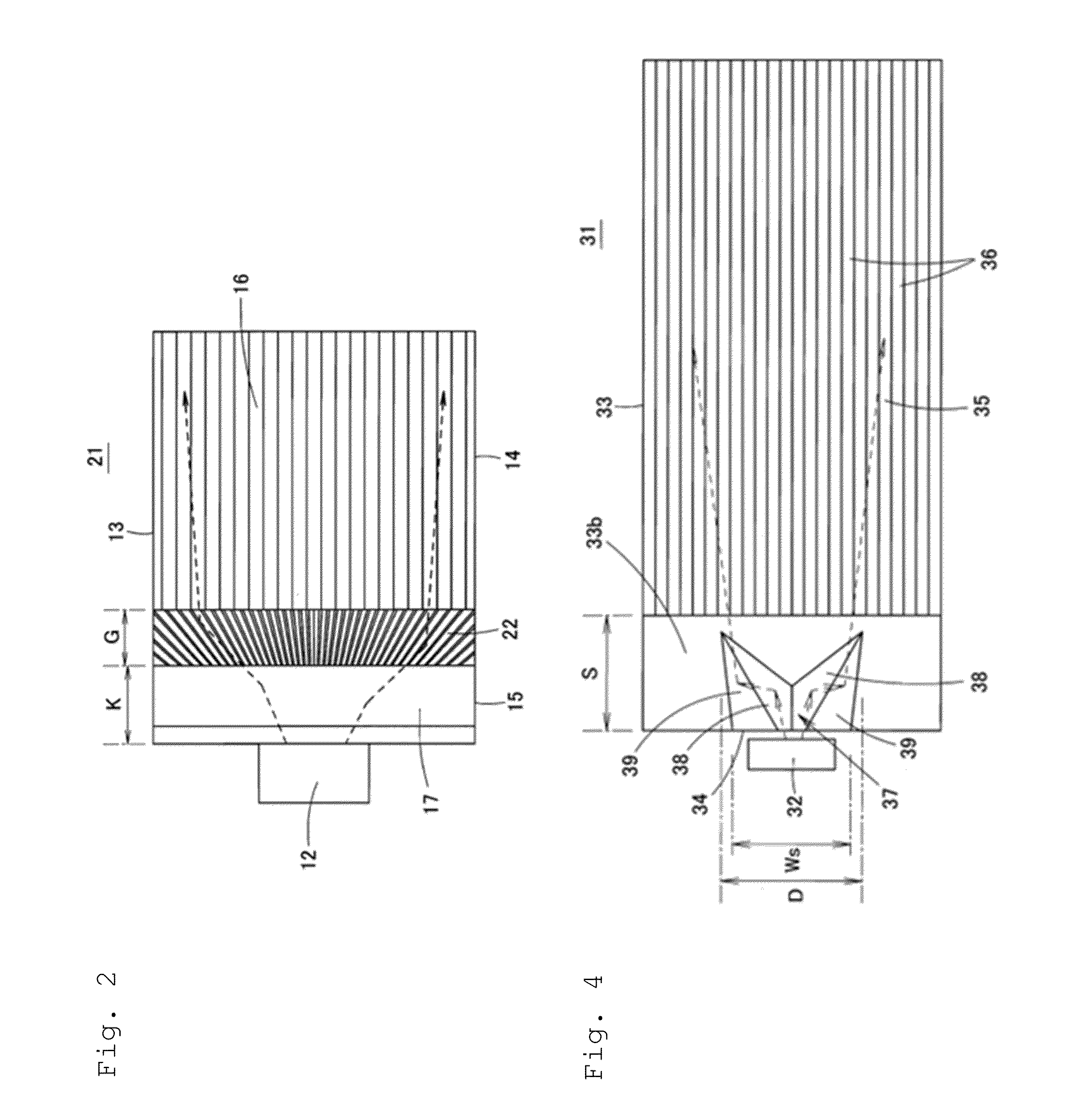
[0076]The light guided through the light incident end portion 33b is reflected by the directivity changing unit 37 to undergo widening of the directivity in the plane perpendicular to the light emitting surface 35. The resultant light reflected by the directivity changing unit 37 ent...

third embodiment

[0079]FIG. 17A is a perspective view of a light guide plate 61 according to a third embodiment of the present invention as viewed from its top surface. FIG. 17B is a perspective view of the light guide plate 61 as viewed from its lower surface. The light guide plate 61 includes a directivity changing unit 37 on its lower surface and a lenticular lens 36 on its top surface.


PUM


Abstract

A light guide plate has a light guide plate member having a light incident surface on an end face of the light guide member, and a light emitting surface on a front surface of the light guide plate member, wherein the light incident surface is structured to have light incident thereon, and wherein the light emitting surface is structured to widen and emit light incident thereon out of the light guide plate member, and a directivity changing unit arranged on a light incident end portion of the light guide plate member on the front surface or a back surface of the light guide plate member. The directivity changing unit has a first inner inclined surface and a second inner inclined surface that change a directivity of the incident light within the directivity changing unit to widen the light laterally with respect to a direction perpendicular to the light incident surface.

Description

BACKGROUND[0001]1. Field[0002]The present invention relates to a light guide plate and a surface light source device, and more particularly, to a surface light source device used as a backlight of a liquid crystal display, and a light guide plate included in the surface light source device.[0003]2. Related Art[0004]The recent trend toward thinner mobile devices requires thinner surface light source devices incorporated in the mobile devices. Such a thinner surface light source device needs a thinner light guide plate. Although a light guide plate, which is a flat plate, can reduce its thickness, a light source such as an LED has a limitation in reducing its height. The thickness of the flat, thin light guide plate at its end face (light incident surface) can be greater than the height of the light source arranged to face the light incident surface of the light guide plate. In this case, the light source protrudes above the top surface of the light guide plate. Light emitted from the...

Claims


Application Information

Patent Timeline
Patent Type & Authority Applications(United States)
IPC IPC(8): F21V8/00
CPCG02B6/003G02B6/002G02B6/0038
Inventor SHINOHARA, MASAYUKIKITAMURA, NORIKAZUHIROTA, KAZUHIDE
Owner ORMON CORP
Why Eureka
Try Eureka