Heat sink for notebook computer

Inactive Publication Date: 2011-03-31
TING SHAO CHIEH
View PDF12 Cites 19 Cited by
  • Summary
  • Abstract
  • Description
  • Claims
  • Application Information

AI Technical Summary

Benefits of technology

[0014]The primarily objective of the present invention is to provide a heat sink having better heat dissipation efficiency, which is able to maintain a superposed configuration, as far as possible, between an air inlet of a notebook computer and an air outlet of a heat sink, and thereby enable airflow to effectively enter the interior of the notebook computer when a fan in the interior of the heat sink is rotating. The heat sink primarily comprising a perforated plate, a base, a displacement control assembly, a plurality of rollers, a plurality of fan assemblies, a supporting frame, a plurality of rubber studs, a plurality of antislip stop posts, a plurality of wire fasteners, and a plurality of pads.
[0015]Another objective of the present invention lies in enabling the user to allocate the positions of the fan assemblies of the heat sink according to different models of notebook computers through a combined configurat

Problems solved by technology

Heat dissipation problems have for a long time been the most troublesome problem for electric appliances, especially with the more precision electronic products.
Moreover, heat dissipation problems often obstruct development of electronic products.
However, because a considerably large amount of heat energy is produced when the CPU is operating, thus, the higher the CPU speed, correspondingly, the larger the heat dissipation problem is.
Hence, hindrance of the heat dissipation problem is the biggest stumbling block to development of the notebook computer.
The traditional method of the upward blow type fan is to fixedly secure a heat dissipation fan to a position on a base, which thus makes it impossible to arbitrarily change position thereof.
Hence, such a method is only suitable for a few computer models, and is unable to effectively direct air into the interior of the notebook computer, and thus unable to provide an effective heat sink function for notebook computers.
The heat sink method of a downward extraction type fan primarily uses rotation of a fan to draw

Method used


Image

  • Heat sink for notebook computer
  • Heat sink for notebook computer
  • Heat sink for notebook computer

Examples


Example

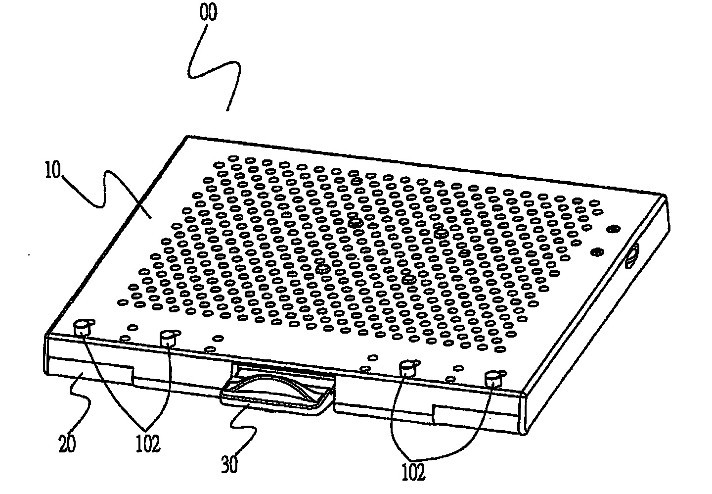
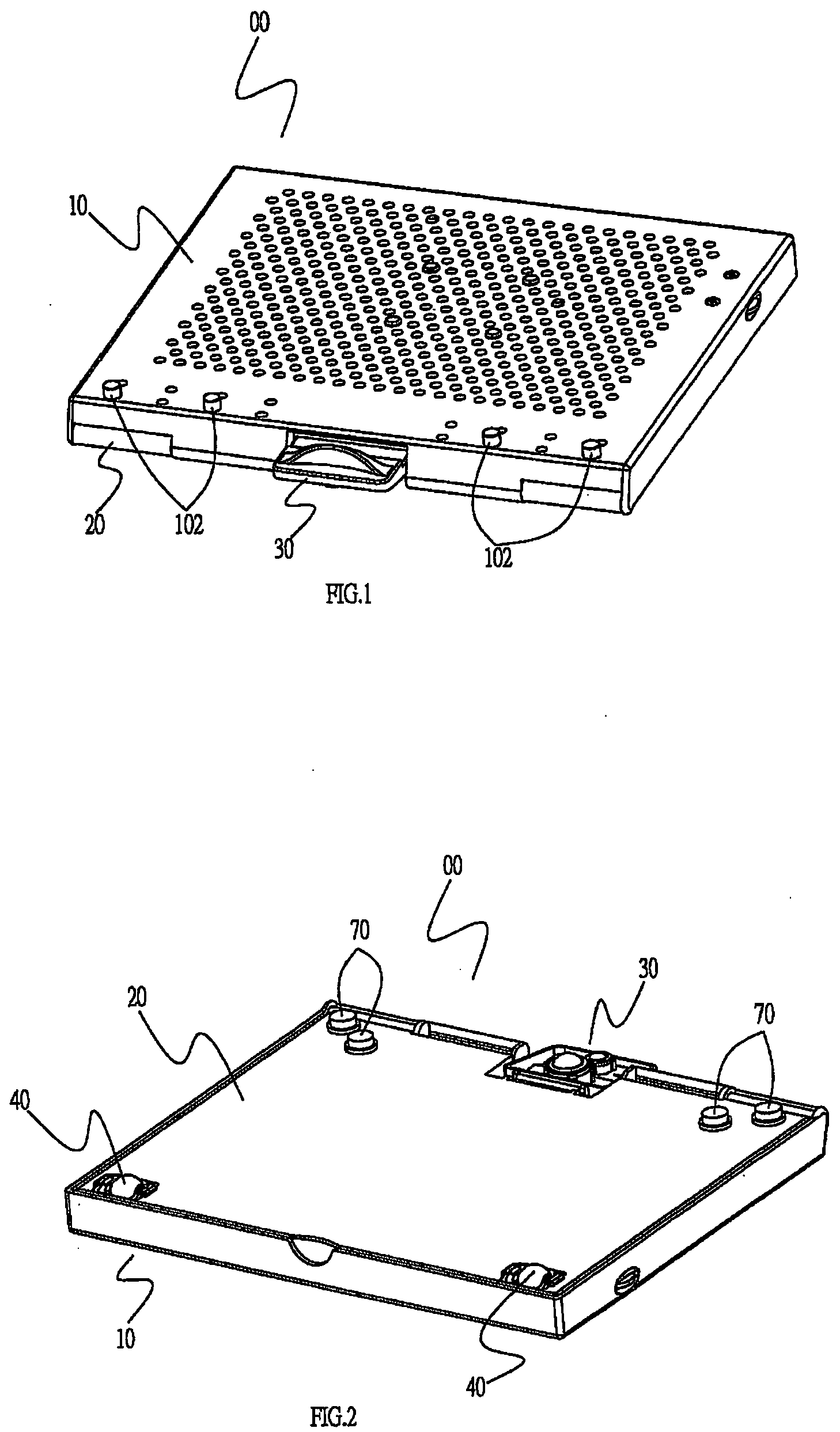
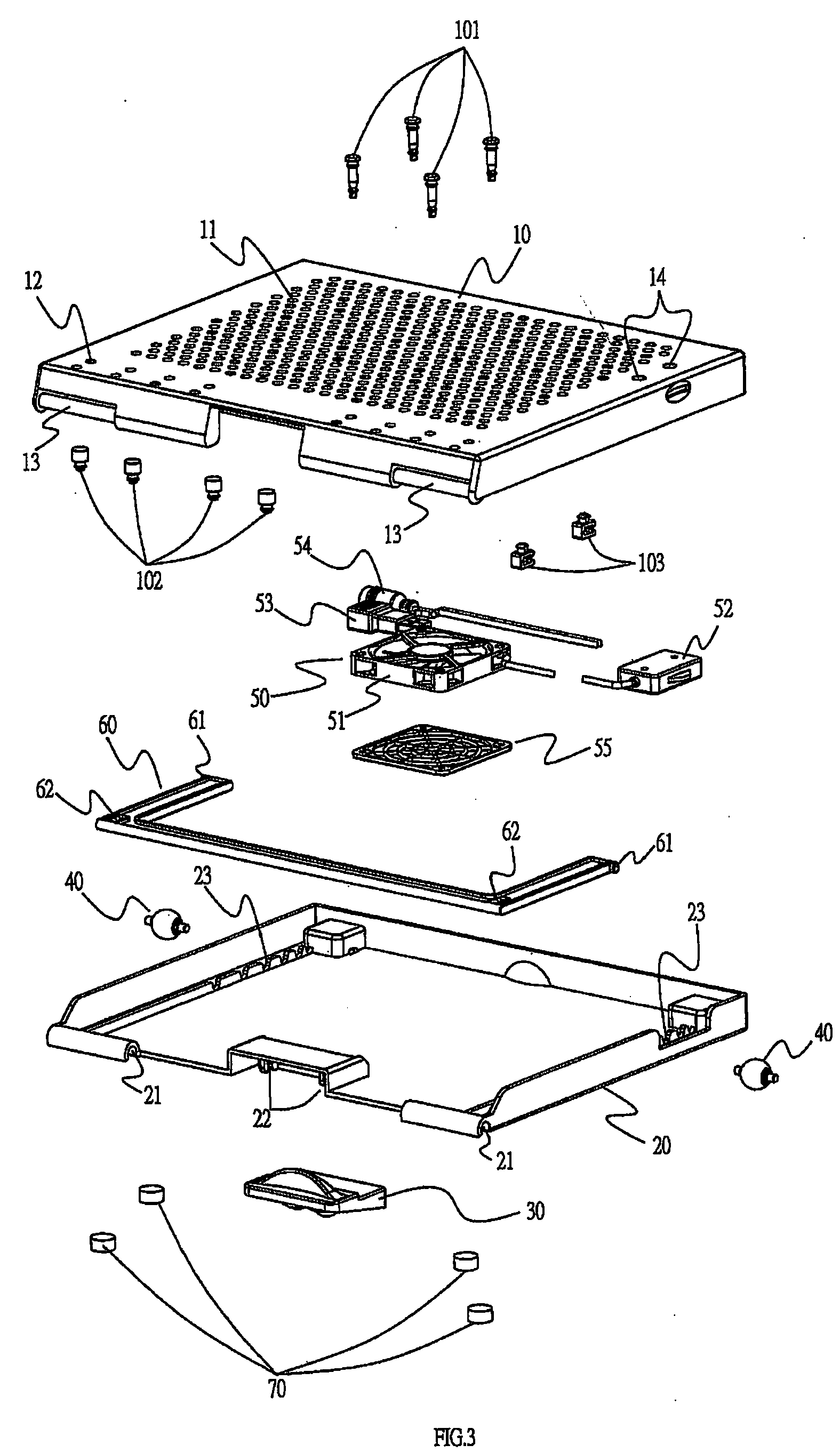
[0026]Referring first to FIG. 1, FIG. 2 and FIG. 3, which disclose elevational schematic views and an exploded schematic view of a heat sink of the present invention, and it can be seen from the drawings that a heat sink 00 of the present invention comprises a perforated plate 10, a base 20, a displacement control assembly 30, a plurality of rollers 40, a plurality of fan assemblies 50, a supporting frame 60, a plurality of rubber studs 101, a plurality of antislip stop posts 102, a plurality of wire fasteners 103 and a plurality of pads 70. Wherein:

[0027]Referring together to FIG. 5 and FIG. 6B, the perforated plate 10 is used to enable a notebook computer to be superposed thereon. The perforated plate 10 is provided with a plurality of holes 11, and a plurality of antislip stop post locating holes 12. Moreover, the perforated plate 10 is further provided with a pivot 13 at each of two sides thereof, two air speed regulator fixing holes 14, two supporting structures 15 for the supp...


PUM


Abstract

The present invention is able to guide the wind produced by a fan interior of a heat sink when rotating to the interior of a computer, and discharge heat energy from the interior of the computer. Moreover, a user can easily adjust and fix air outlets of fan assemblies to corresponding positions beneath air inlets of a notebook computer to achieve optimum heat dissipation effectiveness. In addition, the user can adjust the screen viewing angle and height of the notebook computer, as well as make forward and rearward displacement or right and left rotation of the computer, thereby facilitating operational use by the user.

Description

BACKGROUND OF THE INVENTION[0001](a) Field of the Invention[0002]The present invention relates to a notebook computer heat sink, and more particularly to a heat sink able to effectively cause air flow to enter the interior of a notebook computer and discharge heat energy from the interior of the notebook computer. The heat sink is provided with fan assemblies that can be assembled at a multitude of positions; moreover, the heat sink is applicable for use with different models of notebook computers, can be adjusted to different viewing angles and heights and enables forward and rearward displacement or left and right rotation on a worktop surface.[0003](b) Description of the Prior Art[0004]Heat dissipation problems have for a long time been the most troublesome problem for electric appliances, especially with the more precision electronic products. Moreover, heat dissipation problems often obstruct development of electronic products.[0005]Development of the technological era has brou...

Claims


Application Information

Patent Timeline
IPC IPC(8): F28F13/00
CPCG06F1/203
Inventor TING, SHAO-CHIEH
Owner TING SHAO CHIEH
Why Eureka
Try Eureka