
Heat dissipation device with supercharger

A heat dissipation device and supercharger technology, which can be applied in the direction of cooling/ventilation/heating transformation, electrical components, electrical equipment structural parts, etc., and can solve problems that affect operating efficiency and product service life

Pending Publication Date: 2020-07-31
楚岳(惠州)热传科技有限公司
View PDF0 Cites 0 Cited by
  • Summary
  • Abstract
  • Description
  • Claims
  • Application Information

AI Technical Summary

Problems solved by technology

[0002] The 21st century is an era of advanced electronic information. Due to the characteristics of semiconductors, various products such as laptop computers, personal digital assistants (PDAs), servers, smart mobile phones and smart electrical appliances are not available. At the same time, some products are also designed to be light, thin, short, and small, so that people can carry them around, use them at any time and obtain information in real time, and the characteristics of semiconductors are also used in the automatic operation of many smart machines. Control equipment; the above-mentioned electronic information products and automatic control equipment need to use the central processing unit (CPU) and its peripheral electronic components to control the operation. The central processing unit and the electronic components will generate high temperature during operation, which will affect the operation. Efficiency and product life, so how to effectively cool down the central processing unit and the electronic components has always been one of the main issues that the industry wants to solve

Method used


Image

  • Heat dissipation device with supercharger
  • Heat dissipation device with supercharger

Examples


Embodiment 1

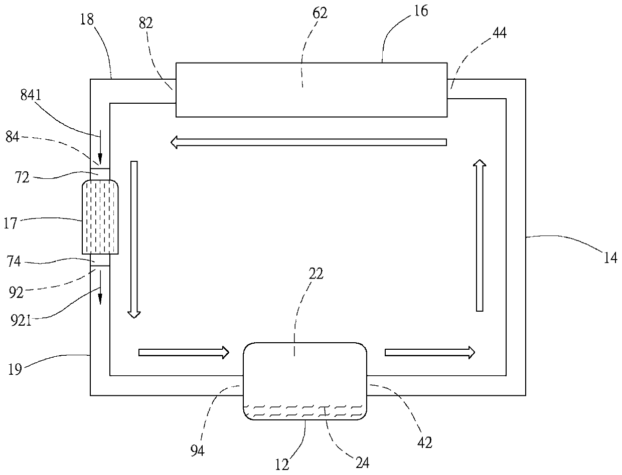
[0025] See figure 1 , The present invention provides a technical solution: a cooling device with a supercharger.

[0026] Next, the specific structure of a cooling device with a supercharger and the connection relationship of each component will be described:

[0027] The cooling device with supercharger of the present invention at least comprises a heat absorber 12, a first pipeline 14, a radiator 16, a second pipeline 18, a supercharger 17 and a third pipe Road 19, wherein the heat absorber 12, the first pipeline 14, the radiator 16, the second pipeline 18, the supercharger 17 and the third pipeline 19 are connected to form a closed circuit.

[0028] The heat absorber 12 is provided with a first internal space 22 for accommodating a liquid 24, and the heat absorber 12 is used to receive heat from a heat source (not shown in the figure) in a conductive manner, so that the liquid 24 exchanges heat with the heat And output high-temperature liquid-phase fluid, gas-phase fluid ...

Embodiment 2

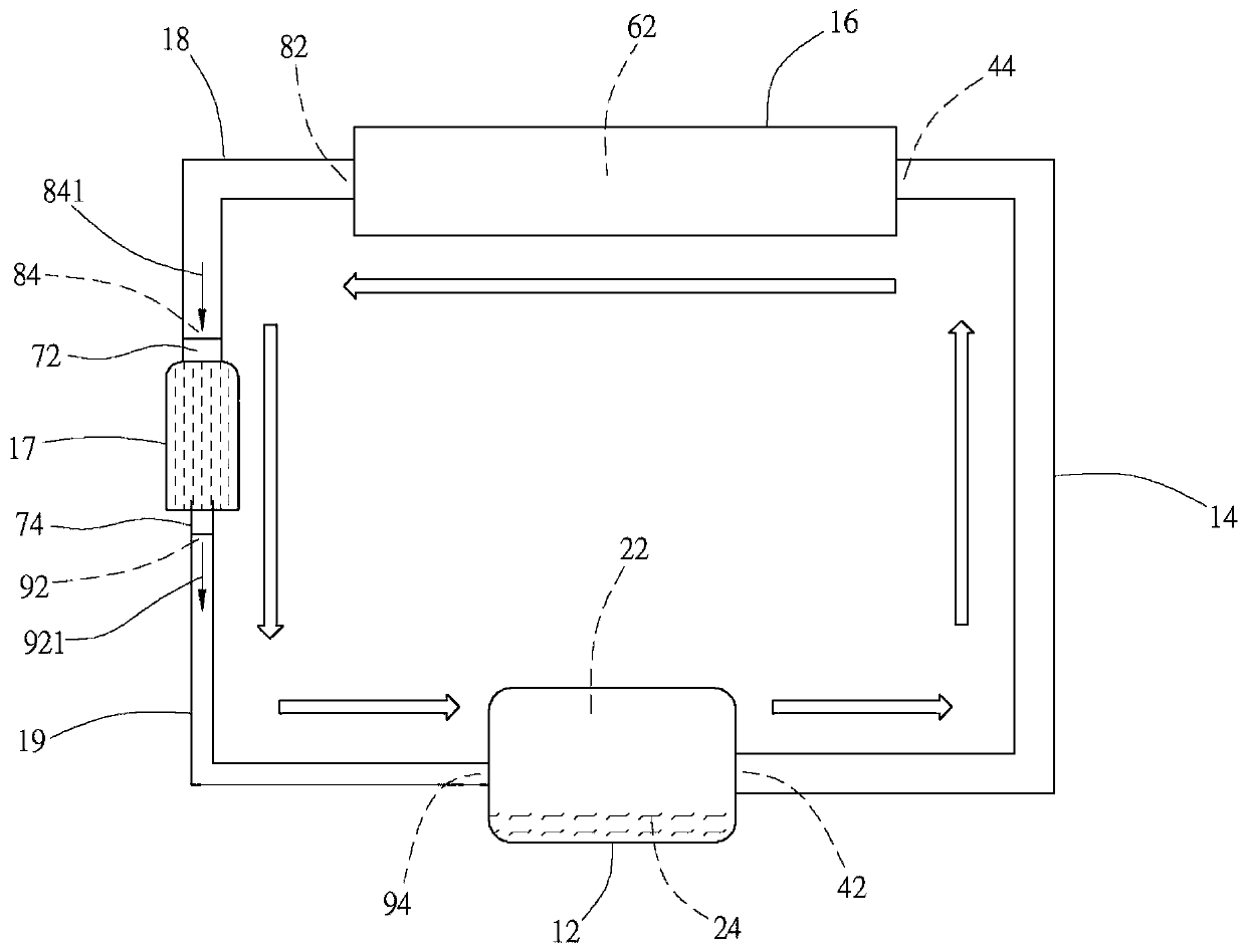
[0036] See figure 2 , the present invention provides a technical solution: a heat dissipation device with a supercharger, which at least includes a heat absorber 12, a first pipeline 14, a radiator 16, a second pipeline 18, a supercharger 17 and a third pipeline 19, wherein the heat absorber 12, the first pipeline 14, the radiator 16, the second pipeline 18, the supercharger 17 and the third pipeline 19 are connected form a closed loop.

[0037] The heat absorber 12 is provided with a first inner space 22 for containing the liquid 24. The heat absorber 12 is used to receive heat from a heat source (not shown in the figure) in a conductive manner, so that the liquid 24 exchanges heat with the heat. When outputting high temperature liquid phase fluid, gas phase fluid or fluid mixed with liquid phase and gas phase, the boiling point of the liquid 24 can be less than 100 degrees Celsius or less than 50 degrees Celsius, and the heat source can be a central processing unit (CPU), ...

Embodiment 3

[0046] The present invention provides a technical solution: a heat dissipation device with a supercharger, which at least includes a heat absorber 12, a first pipeline 14, a radiator 16, a second pipeline 18, and a supercharger 17 and a third pipeline 19, wherein the heat absorber 12, the first pipeline 14, the radiator 16, the second pipeline 18, the supercharger 17 and the third pipeline 19 are connected to form a closed loop.

[0047] The heat absorber 12 is provided with a first inner space 22 for containing the liquid 24. The heat absorber 12 is used to receive heat from a heat source (not shown in the figure) in a conductive manner, so that the liquid 24 exchanges heat with the heat. When outputting high temperature liquid phase fluid, gas phase fluid or fluid mixed with liquid phase and gas phase, the boiling point of the liquid 24 can be less than 100 degrees Celsius or less than 50 degrees Celsius, and the heat source can be a central processing unit (CPU), a chip (IC...


PUM


Abstract

The invention discloses a heat dissipation device with a supercharger. The heat dissipation device comprises a heat absorber, a first pipeline, a radiator, a second pipeline, the supercharger and a third pipeline. The heat absorber is used for accommodating fluid and receiving heat from a heat source, so that the fluid exchanges heat with the heat source to be output; one end of the first pipelinecommunicates with one side of the heat absorber; the radiator is communicated with the other end of the first pipeline; one end of the second pipeline is communicated with the radiator; one end of the supercharger is communicated with the other end of the second pipeline; and one end of the third pipeline is communicated with the other end of the supercharger, and the other end of the third pipeline is communicated with the other side of the heat absorber. Therefore, the heat dissipation device is realized, the material and structural characteristics are utilized, the working fluid is drivenby the better effect, the drainage effect is formed, the fluid is driven by the better effect, and the heat absorption and dissipation efficiency is better.

Description

technical field [0001] The invention relates to the field of cooling devices, in particular to a cooling device with a supercharger. Background technique [0002] The 21st century is an era of advanced electronic information. Due to the characteristics of semiconductors, various products such as laptop computers, personal digital assistants (PDAs), servers, smart mobile phones and smart electrical appliances are not available. At the same time, some products are also designed to be light, thin, short, and small, so that people can carry them around, use them at any time and obtain information in real time, and the characteristics of semiconductors are also used in the automatic operation of many smart machines. Control equipment; the above-mentioned electronic information products and automatic control equipment need to use the central processing unit (CPU) and its peripheral electronic components to control the operation. The central processing unit and the electronic compo...

Claims


Application Information

Patent Timeline
Patent Type & Authority Applications(China)
IPC IPC(8): H05K7/20
CPCH05K7/20254H05K7/20272
Inventor 黄哲圣周华军
Owner 楚岳(惠州)热传科技有限公司
Learn More