Supercharger for an engine

a supercharger and engine technology, applied in the direction of machines/engines, combustion engines, exhaust treatment, etc., can solve the problems of increasing the exhaust flow rate and subsequently increasing the turbine driving force, the structure of the system including the variable-geometry turbocharger is typically complicated, and the engine torque cannot be increased in a broad engine speed range that includes both low and high engine speeds. , to achieve the effect of improving charging performance, improving scavenging performance, and broad operating rang

Active Publication Date: 2009-04-16
MAZDA MOTOR CORP
View PDF6 Cites 68 Cited by
  • Summary
  • Abstract
  • Description
  • Claims
  • Application Information

AI Technical Summary

Benefits of technology

[0049]This embodiment can compensate for diminished engine output by operating an electric supercharger when intake and exhaust valves are operated with an overlap period and where afterburning does not occur.
[0050]As described above, when the overlap period is enlarged while performing independent exhaust throttle control, there may be a torque stationary range between an overlap amount for improving scavenging performance and an overlap amount for improving charging performance by afterburning phenomenon. Scavenging performance may be saturated and afterburning may occur within this range.
[0051]Therefore, in an embodiment wherein the intake and the exhaust valves are operated within the above-described range, an electric supercharger may sustain the charging performance to maintain engine output within a broad operating range. Further, if the electric supercharger is only operated in the above-described range, supercharger operation can be reduced.

Problems solved by technology

Although a turbocharger can obtain high charging pressure efficiently, it cannot necessarily increase engine torque in a broad engine speed range that includes both low and high engine speeds.
However, many engine systems need to increase engine torque over a large engine speed range from low engine speed to high engine speed.
In a low engine speed range, engine torque may be increased by reducing the flap opening, which increases the exhaust flow rate and subsequently increases the turbine driving force.
However, a system including a variable-geometry turbocharger typically has a complicated structure.
Further, the large size of these devices may crowd the engine room.
First, the ejector effect can increase the turbine flow of the turbocharger, which is the amount of exhaust gas supplied to a turbocharger.
Exhaust gas extracted by the ejector may serve as scavenged exhaust gas, which may decrease the exhaust resistance.
Thus, increasing the charging pressure with the ejector effect is unnecessary above the intercept point.
Further, independent exhaust throttle control when the engine speed is above the intercept point may lead to an undesirable exhaust resistance.
However, the weakened blow-down gas flow may be less effective as a driving fluid for the ejector effect, which may diminish the capabilities of the independent exhaust throttle control.
However, the inventors herein have recognized that, if the overlap period continues to be increased after the engine output reaches the threshold described above, unburned fuel will be exhausted into the exhaust passage.
This unburned fuel may combust at the upstream side of said exhaust turbocharger, which results in the afterburning phenomenon.
Scavenging performance may be saturated and afterburning may occur within this range.

Method used


Image

  • Supercharger for an engine
  • Supercharger for an engine
  • Supercharger for an engine

Examples


embodiment 1

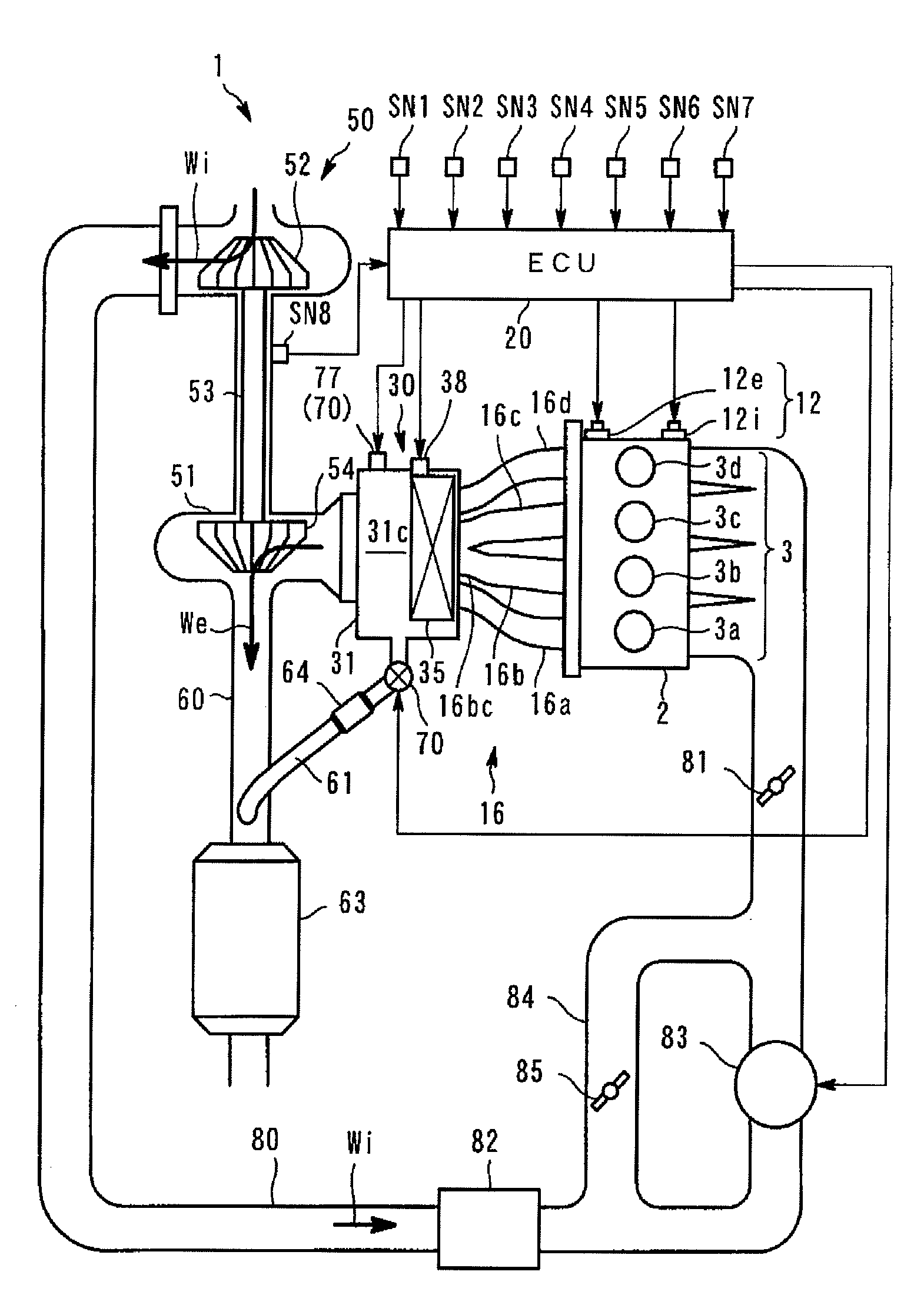
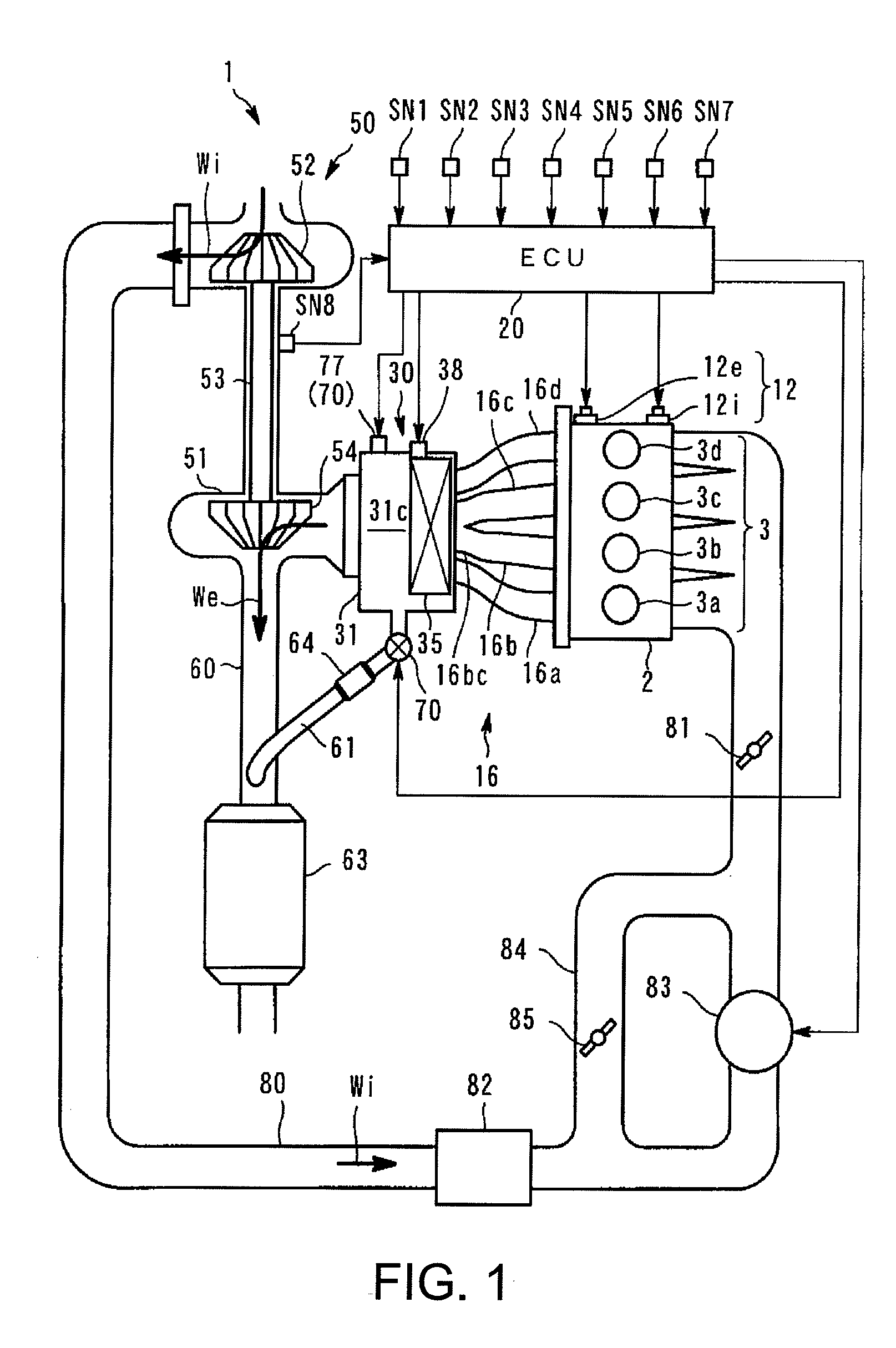
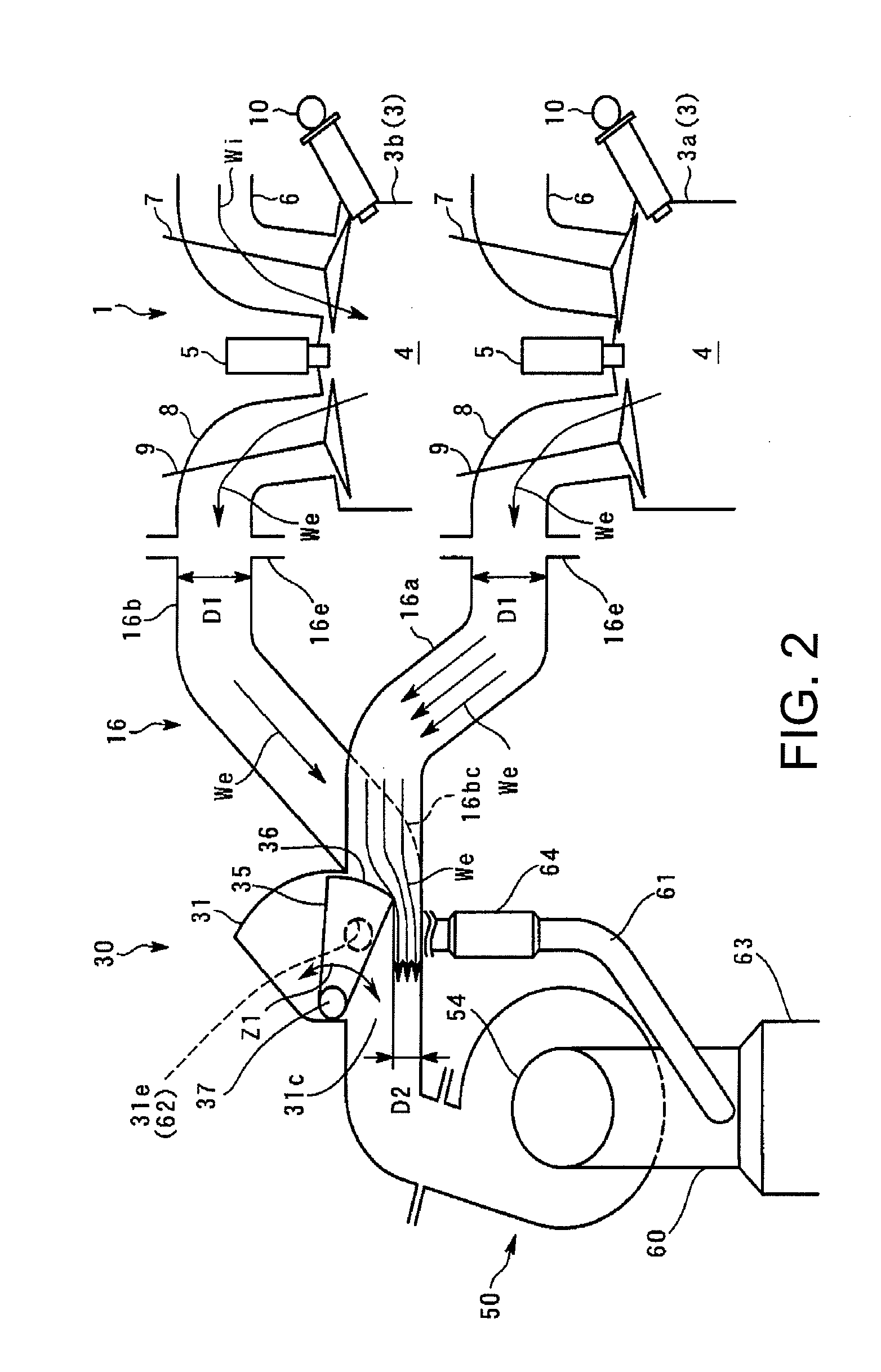
[0082]FIG. 1 is a schematic view showing an engine system with a supercharger according to an embodiment (hereinafter, simply referred to as an “engine”). FIG. 2 is a partial side cross-section of FIG. 1.

[0083]The engine system with the supercharger is provided with an in-line four-cylinder engine 1 of four cycle.

[0084]In this embodiment, the supercharger has a simple configuration using a single turbocharger 50. The turbocharger has characteristics capable of obtaining a high supercharge performance over a wide range from a lower-speed range to a higher-speed range, and generating a high torque throughout the entire range.

[0085]To achieve this, the supercharger primarily provides the following two technical features: (1) improvement in the supercharge performance with dynamic-pressure supercharge; and (2) an independent exhaust choke control using independent exhaust passages and a variable exhaust valve 30. These features will be described in detail later, and first, a configurati...

embodiment 2

[0204]Next, another embodiment of the present invention will be described. The second embodiment is similar to that of the first embodiment in that it has the device configuration shown in FIGS. 1-10, performs the dynamic-pressure supercharge and the independent exhaust choke control, and performs the valve-timing change control. In the first embodiment, the independent exhaust control is only performed in the lower-speed supercharging range A3. However, in this embodiment, the control is also performed in the natural intake range, and in addition, a control to increase the overlapped amount is performed. This takes advantage of the effect of the independent exhaust choke control in which the backward flow of the exhaust gas is controlled by the ejector effect even if the overlapped amount is increased. As a result, an overlap expansion response at the time of an acceleration request can be improved.

[0205]Referring to FIG. 13, the features of this embodiment will be described in det...

embodiment 3

[0214]FIG. 20 is a characteristic plot showing an example setting for an operating range in which a control according to an operating condition according to a third embodiment of the present invention is performed, which has the configuration of FIGS. 1-10. In FIG. 20, the horizontal axis represents an engine speed Ne (rpm), and the vertical axis represents a required torque τ (N-m). The characteristic WOT shows a maximum load torque (engine-fully-open operating range). Supercharge operating ranges R10, R11, R20, and R21 on a higher-load side, and the natural-intake operating ranges R12 and R22 on a lower-load side are set bordering on the characteristic NA.

[0215]Referring to FIG. 20, in this embodiment, among the operating ranges R10-R22, an independent exhaust choking mode is performed in the supercharge operating ranges R10 and R11 on the lower-speed side, and the natural-intake operating range R12. In the independent exhaust choking mode, ECU 20 as a variable exhaust valve contr...


PUM


Abstract

An engine system with a turbocharger is provided. The system may include an exhaust manifold having plural independent exhaust passages, each of the exhaust passages being connected to an exhaust port of a corresponding engine cylinder. The system may further include a collective part formed by gathering said independent exhaust passages in said exhaust manifold or on a downstream side of said exhaust manifold. The system may further include an exhaust turbocharger connected to a downstream side of said collective part. The system may further include a variable exhaust valve for changing each passage cross-sectional area of said independent exhaust passage at an upstream side of said collective part. The system may further include a controller for controlling said variable exhaust valve, wherein said controller is configured to perform independent exhaust throttle control for reducing a passage cross-sectional area of at least one of said independent exhaust passages.

Description

TECHNICAL FIELD[0001]This invention relates to an engine system with a supercharger.BACKGROUND AND SUMMARY[0002]Superchargers are known to increase engine output torque by increasing the intake air pressure. One well-known example of a supercharger is an exhaust turbocharger, hereinafter described as “a turbocharger.”[0003]Turbochargers typically include a turbine wheel (“a turbine”) in an exhaust passage coupled by a shaft to a compressor wheel (“a compressor”). In operation, exhaust gas passing by the turbine spins a shaft which rotates the compressor and increases the intake pressure. The pressure increase in the intake air is sometimes referred to as charging the air, and the compressor output may be called charge air.[0004]Although a turbocharger can obtain high charging pressure efficiently, it cannot necessarily increase engine torque in a broad engine speed range that includes both low and high engine speeds. Generally, a small-sized turbocharger increases the engine torque ...

Claims


Application Information

Patent Timeline
Patent Type & Authority Applications(United States)
IPC IPC(8): F02D23/00
CPCF01N13/107F01N2240/36F02B37/004F02B37/04F02B39/10F02D9/04F02D9/1035F02D9/103F02D9/1065Y02T10/18F02D13/0219F02D13/0261F02D9/101Y02T10/12
Inventor YAMAGATA, NAOYUKIFUJII, MIKIHITOMASUYAMA, SUSUMU
Owner MAZDA MOTOR CORP
Why Eureka
Try Eureka