
Downhole bypass valve

a bypass valve and downhole technology, applied in the field of downhole tools, can solve problems such as tool “dormant”, and achieve the effect of facilitating fluid actuation of the tool

Inactive Publication Date: 2005-04-07
SYMBOL TECH INC
View PDF31 Cites 71 Cited by
  • Summary
  • Abstract
  • Description
  • Claims
  • Application Information

AI Technical Summary

Benefits of technology

[0017] Unlike a ball or other flow occluding tool activating member, which will substantially occlude the string bore, the use of a tool activating sleeve allows fluid to continue to flow through the string and tool, and may permit access to the section of the bore below the tool. Also, the use of a sleeve allows fluid to be circulated while the sleeve is moving down through the string; unlike a ball or other flow-occluding device, the sleeve will not induce a large hydraulic shock on engaging the tool.
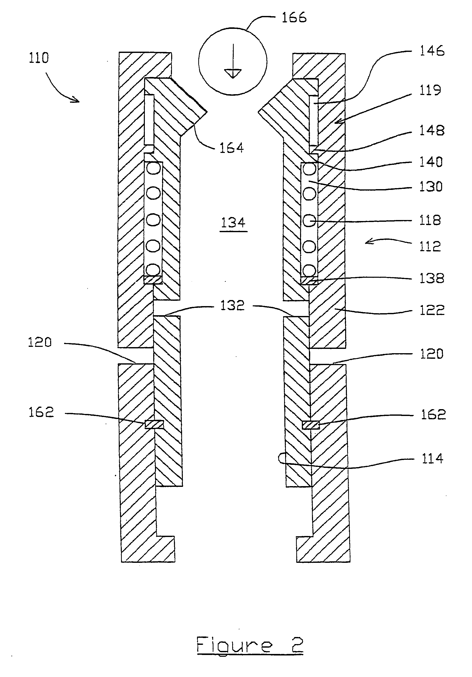
[0018] The sleeve may define a flow restriction, such as a nozzle, which flow restriction permits or facilitates fluid actuation of the tool. Alternatively, the restriction may be defined by another part of the tool, which part is fixed before the sleeve is caught in the tool. Two or more axially spaced flow restrictions may be provided, allowing creation of a greater fluid pressure force without a significant restriction in bore diameter.
[0035] This method is particularly useful in drilling or circulating operations, as there is no requirement to stop fluid circulation as the device moves through the string and then engages the tool, such that drilling or circulation may continue with the device in the string with a fluid flow rate sufficient to entrain drill cutting and carry them to surface, or to allow continuation of some other fluid circulation-related activity. This contrasts with conventional methods, in which it is necessary to stop or at least substantially reduce circulation to prevent the occurrence of a hydraulic shock on the activating device, typically in the form of a steel ball, engaging the tool. Such a hydraulic shock would result in damage to the ball and tool, and possibly also to the string itself.
[0041] Thus the present invention allows a downhole tool to be disposed in a borehole, which tool may be actuated between two or more tool configurations by supplying fluid to the tool in the borehole and by varying the flow rate of the fluid through the tool.

Problems solved by technology

Thus, prior to the sleeve being caught in the tool, the tool is “dormant”, and may only be actuated after the sleeve is received in the tool.

Method used


Image

  • Downhole bypass valve
  • Downhole bypass valve
  • Downhole bypass valve

Examples


Embodiment Construction

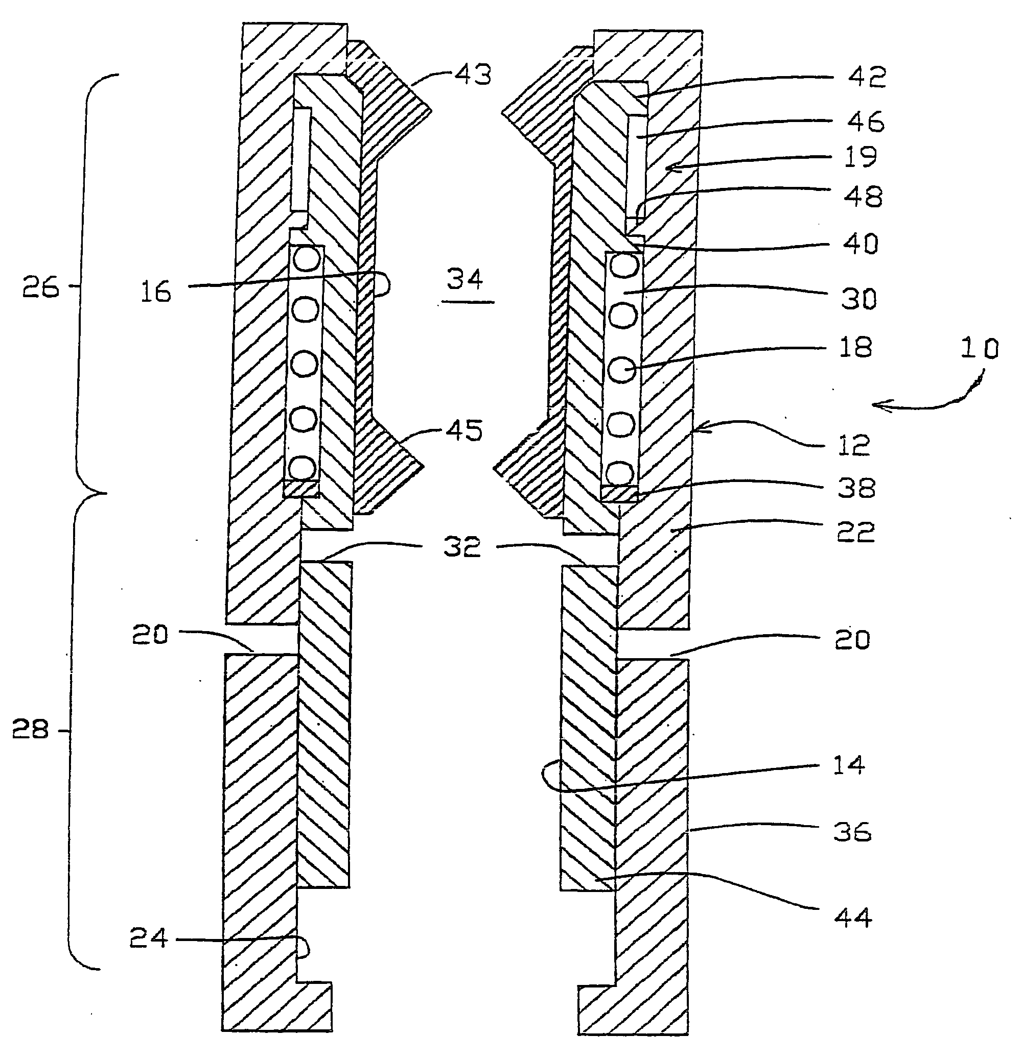
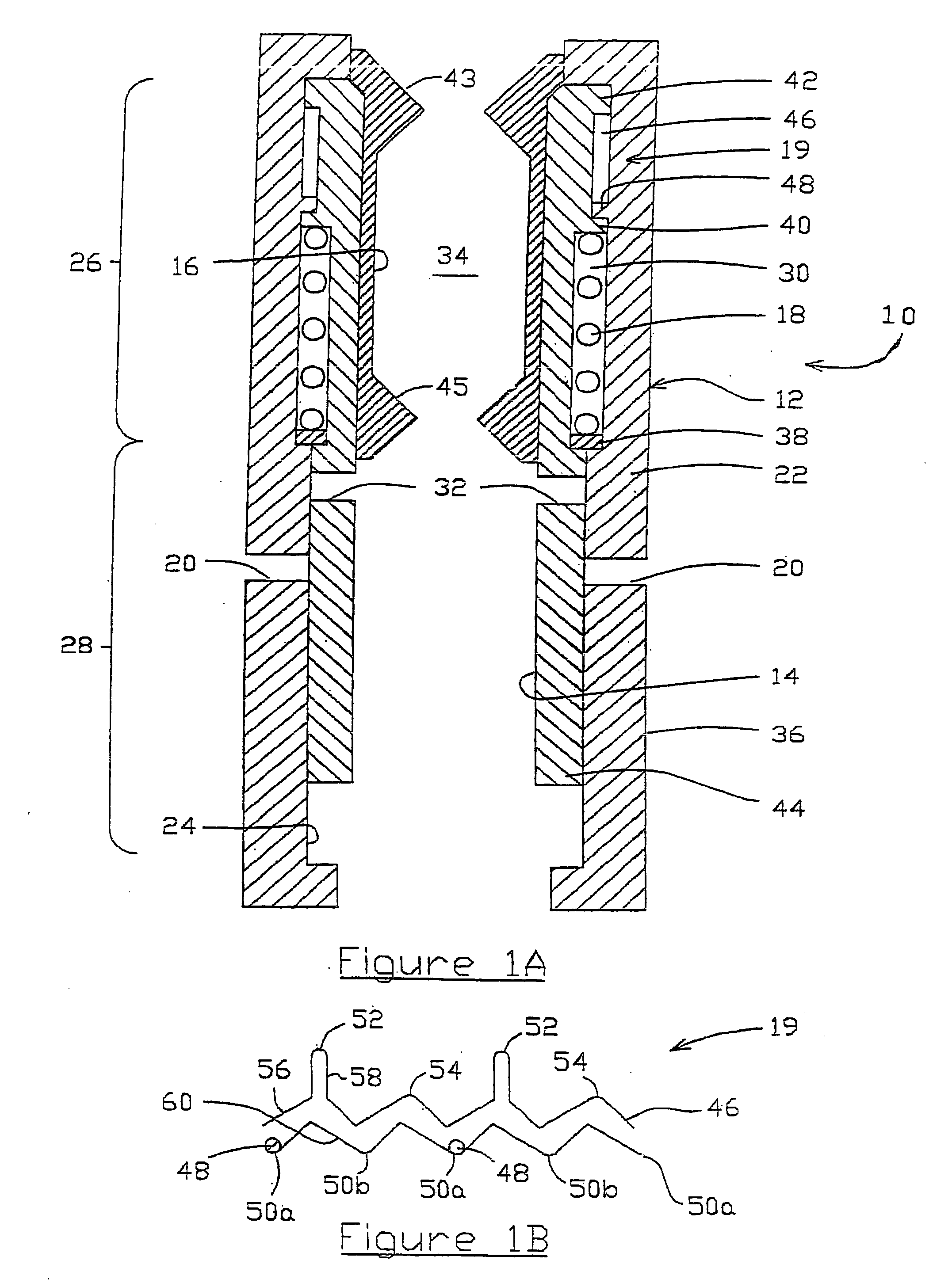
[0060] Referring firstly to FIG. 1, there is shown a longitudinal cross-sectional view of a downhole tool in accordance with an embodiment of the present invention, the downhole tool indicated generally by reference numeral 10. The downhole tool 10 forms part of a drill string (not shown) run into a borehole (not shown) of an oil well, and is coupled at its upper and lower ends to sequential sections of drill string tubing via threaded joints, in a fashion known in the art.

[0061] The downhole tool 10 shown in FIG. 1A is a bypass tool comprising a tubular outer housing 12, a tubular bypass sleeve 14, a tubular flow restriction insert 16, a bypass sleeve spring 18 and a pin and groove assembly indicated generally by reference numeral 19.

[0062] Those of skill in the art will understand that the tool 10 will be provided with a variety of appropriate seals, however in the interest of brevity the individual seals will not be identified and described.

[0063] The tubular outer housing12 i...


PUM


Abstract

A fluid flow actuated downhole tool is configurable in at least a first tool configuration and a second tool configuration. The tool comprises a tubular housing and an activating sleeve, the housing being adapted to catch the sleeve when the sleeve is dropped from surface and the engagement of the sleeve with the housing permitting actuation of the tool between the first and second tool configurations. A flow restriction is provided for permitting fluid flow actuation of the tool when the activating sleeve has been caught in the body.

Description

RELATED APPLICATIONS [0001] This application is a continuation of U.S. patent application Ser. No. 10 / 031,219 filed Jan. 15, 2002, which is a 371 of PCT / GB00 / 02712 filed Jul. 14, 2000, which claims priority of United Kingdom Patent Application 9916513.6 filed Jul. 15, 1999.FIELD OF THE INVENTION [0002] The present invention relates to a downhole tool which is actuatable between at least two tool configurations. In particular, but not exclusively, the present invention relates to a downhole tool comprising a bypass tool for location in a borehole of a well, wherein the bypass tool is actuatable between a closed configuration and an open configuration in response to the flow of fluid through the borehole. BACKGROUND OF THE INVENTION [0003] Bypass tools are typically disposed within a borehole of, for example, an oil well, for selectively allowing fluid communication between a bore defined by a tubular string disposed in the borehole, and an annulus defined between an outer wall of the...

Claims


Application Information

Patent Timeline
Patent Type & Authority Applications(United States)
IPC IPC(8): E21B21/10E21B23/00E21B34/08
CPCE21B21/103E21B34/08E21B23/006
Inventor CHURCHILL, ANDREW PHILIP
Owner SYMBOL TECH INC
Learn More