Method for exhaust gas treatment in a solid oxide fuel cell power plant

a fuel cell power plant and solid oxide technology, applied in the direction of liquefaction, machine/engine, energy input, etc., can solve the problems of small number of gas turbines available, limited future development safety risks of nuclear power plants, etc., to achieve clean and preferably pressurised co2 stream, simple and preferably cheap, and high electrical efficiency

Inactive Publication Date: 2006-06-01
AKER KVRNER ENG & TECH
View PDF9 Cites 72 Cited by
  • Summary
  • Abstract
  • Description
  • Claims
  • Application Information

AI Technical Summary

Benefits of technology

[0026] It is thus desired to find simple and preferably cheap solutions for utilising the remaining unreacted fuel in the anode exhaust gas fo

Problems solved by technology

Nuclear power plants suffer from safety risks and problematic radioactive waste disposal.
Future development of nuclear power plants seems very limited, mostly due to lack of political acceptance.
There is however only a small number of gas turbines available that may use the hydrogen rich gas as fuel.
Therefore, unless modifications/qualifications of other gas turbines are made, this concept will not be available at different scales.
The most economical scales for the components are large and the specific costs and efficiencies will suffer as the scale is reduced.
Another disadvantage of applying conventional CO2 removal solutions in precombustion is that they are operated at low temperature, requiring cooling and reheating of the gas due to the CO2 removal.
This gives a considerable cost penalty in the 10-50 MW scale.
Further, a smaller scale gas turbine with higher specific cost and lower performance must be assumed.
Also the use of CO2/H2O recycle to control the temperature will consume energy at the expense of total efficiency.
Both investment cost and energy consumption are very high for generation of oxygen at the purity and quantity required in Oxyfuel cycles.
These are costly, and more economical ways for the utilization of this heat energy are demanded.
However, the low concentration of CO2 requires large gas handling systems and the treated exhaust gas wil

Method used


Image

  • Method for exhaust gas treatment in a solid oxide fuel cell power plant
  • Method for exhaust gas treatment in a solid oxide fuel cell power plant
  • Method for exhaust gas treatment in a solid oxide fuel cell power plant

Examples


Embodiment Construction

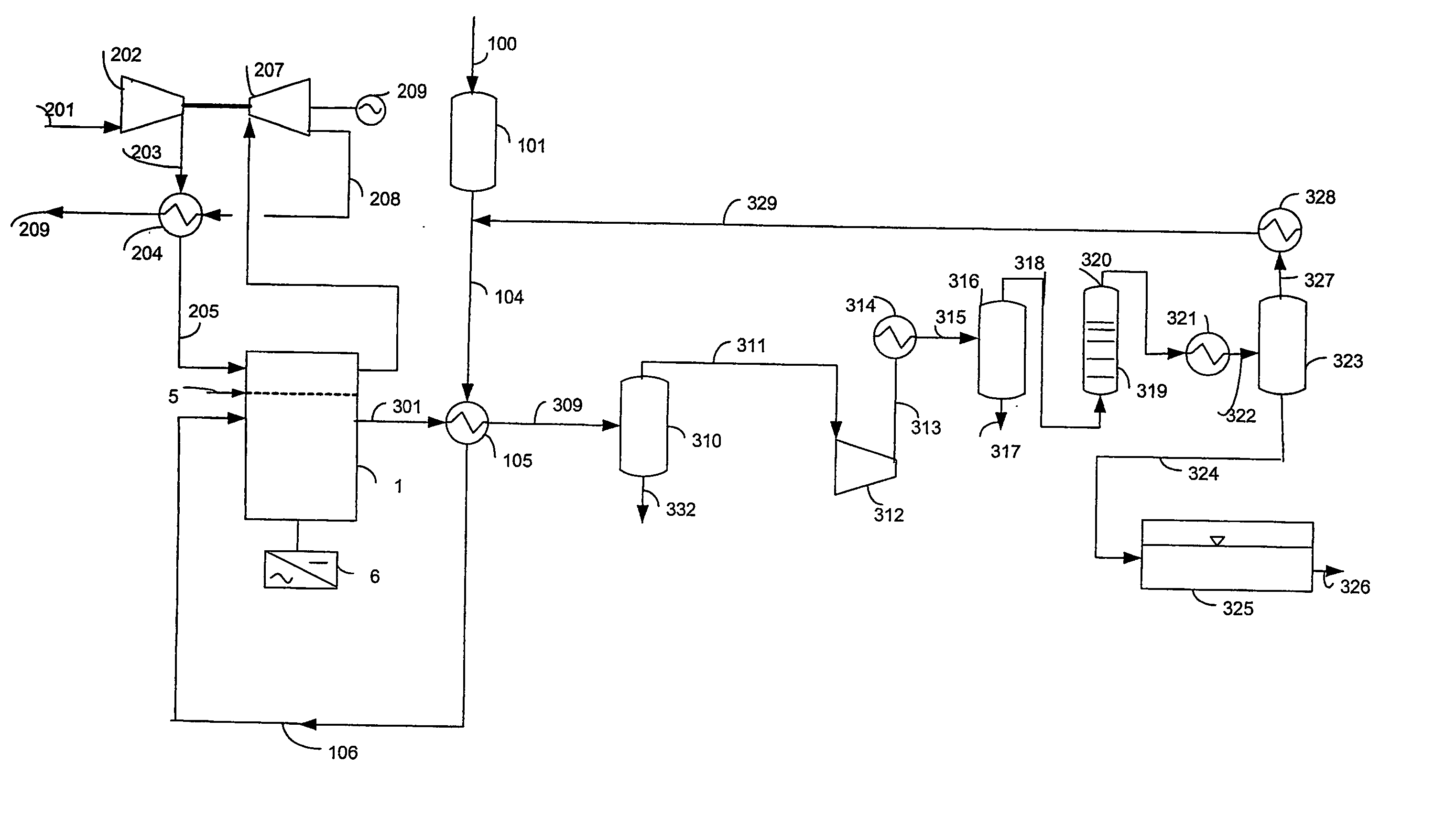
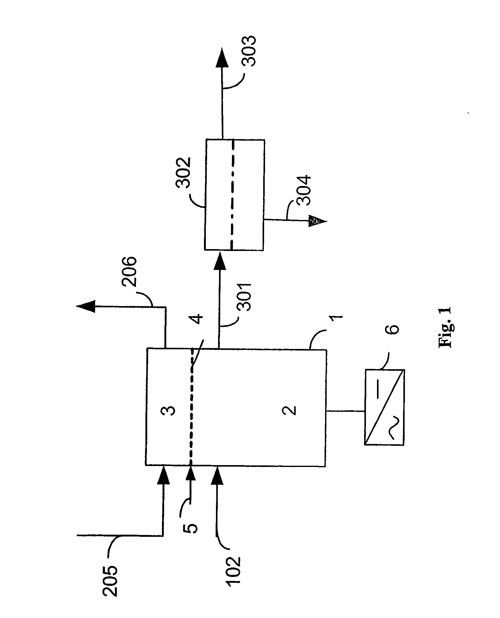
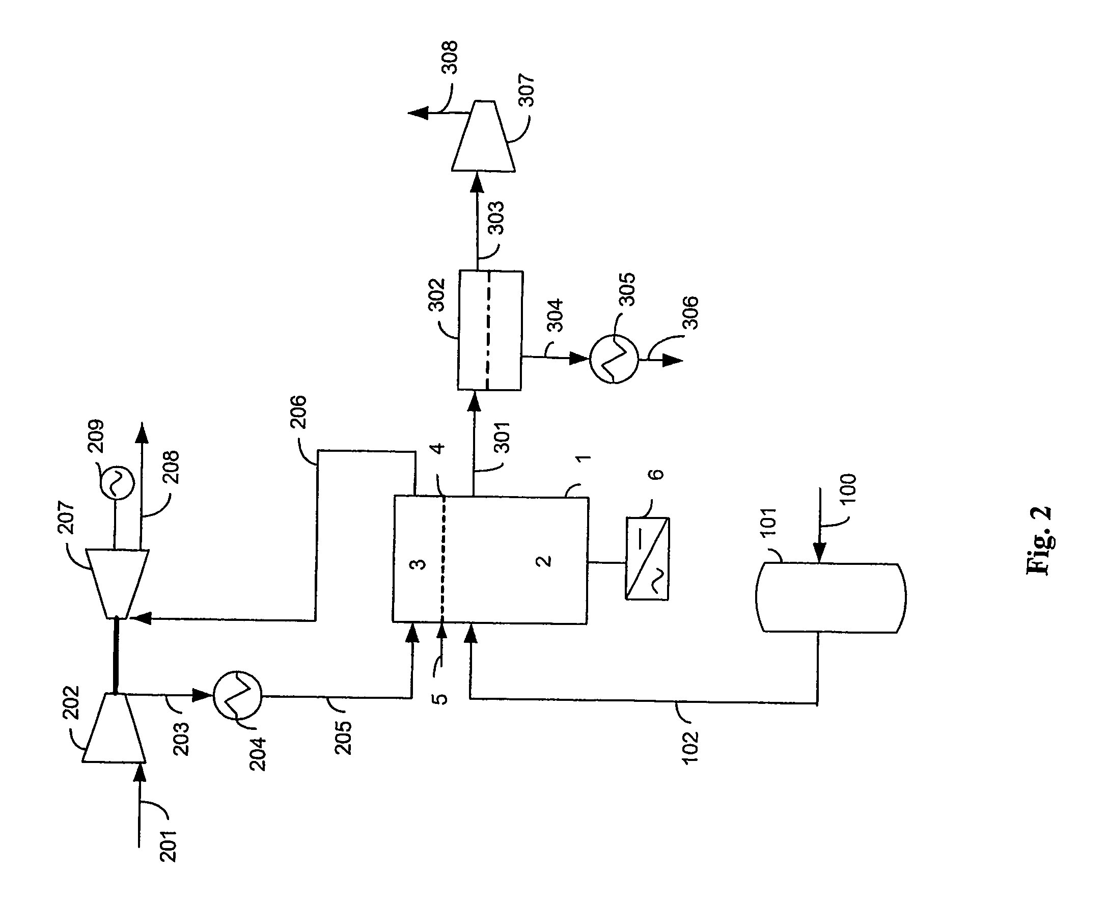
[0046] Referring now in detail to the figures of the drawings, in which identical parts have identical reference symbols, and first, particularly, to FIG. 1. FIG. 1. shows the main principles of the present invention. The main SOFC stack 1, is divided into an anode section 2 and a cathode section 3 by a sealing system 4. This seal system may be a steam seal. Addition of steam, 5, is needed for this particular seal. In order to simplify the schematic, the anode section comprise of all needed reforming steps, as well as optional internal recycle of part of the anode exhaust to the reformers to provide steam required for the steam reforming, or steam addition to the reformers if internal recycle of fuel is omitted, in addition to the fuel cells anode side. No details of the fuel cells are shown. In the present example the fuel cells are of the tubular (one closed end) solid oxide type. Poison-free fuel containing the element carbon 102, typically natural gas, is fed to the anode side 2...


PUM


Abstract

The invention relates to anode exhaust gas treatment methods for solid oxide fuel cell power plants with CO2 capture, in which the unreacted fuel in the anode exhaust (301) is recovered and recycled, while the resulting exhaust stream (303) consists of highly concentrated CO2. It is essential to the invention that the anode fuel gas (102) and the cathode air (205) are kept separate throughout the solid oxide fuel cell stacks (1). A gas turbine (202,207) is included on the air side in order to maximise the electrical efficiency.

Description

BACKGROUND [0001] 1. Field of the Invention [0002] The invention relates to methods for anode exhaust treatment in solid oxide fuel cell power plants where the air stream and fuel stream is kept separate throughout the system. Particularly, the invention relates to solutions for recovering and recycling the unspent fuel from the anode fuel exhaust gas. [0003] 2. Background Information [0004] An increasing demand for electric power combined with increasing environmental awareness has initiated extensive research for developing cost effective and environmentally friendly power generation. Although several renewable power sources are available, only nuclear and hydrocarbon fuelled power plants can supply the bulk of the power being demanded. Nuclear power plants suffer from safety risks and problematic radioactive waste disposal. Future development of nuclear power plants seems very limited, mostly due to lack of political acceptance. Thus, power plants based on fossil fuels are called...

Claims


Application Information

Patent Timeline
IPC IPC(8): H01M8/12H01M8/04H01M2/08B01D53/22C01B3/50F02C6/10F25J3/06H01M8/24
CPCB01D53/22C01B3/501C01B2203/00C01B2203/0233C01B2203/0405C01B2203/0475C01B2203/0495C01B2203/066C01B2203/0833C01B2203/1241C01B2203/127C01B2203/148C01B2203/84C01B2203/86F02C6/10H01M8/04014H01M8/04097H01M8/0668H01M8/0675H01M8/0687H01M8/243Y02E20/14Y02E60/50Y02P20/129Y02P20/151Y02P30/00
Inventor HILMEN, ANNE-METTEURSIN, RORD
Owner AKER KVRNER ENG & TECH
Why Eureka
Try Eureka