High reliability electric drive

a high-reliability, electric drive technology, applied in the direction of machines/engines, magnetic circuit rotating parts, magnetic circuit shapes/forms/construction, etc., can solve the problems of premature device failure, insufficient compactness of electric drives, and small and thinner electronic devices having faster processors, so as to increase the reliability of the system

Inactive Publication Date: 2005-03-17
ROTYS
View PDF5 Cites 41 Cited by
  • Summary
  • Abstract
  • Description
  • Claims
  • Application Information

AI Technical Summary

Benefits of technology

[0026] In the next variant, each of said windings is connected by its controller to an individual power source. This additionally increases reliability of the system.

Problems solved by technology

The trend toward smaller and thinner electronic devices having faster processors renders traditional heat removal cooling systems inadequate.
At the same time the electric drives should have high reliability, since the failure of the electric drives of said cooling systems could cause electronic devices to malfunction during use, or lead to premature device failure.
Many types of electric drives comprise a magnetic rotor and a stator with coils wrapped about some cylindrical core are known, but such electric drives are not compact enough.

Method used


Image

  • High reliability electric drive
  • High reliability electric drive
  • High reliability electric drive

Examples


Embodiment Construction

[0039] Claimed invention will be described in detail below with reference to the accompanying drawings. FIGS. 1-9 show embodiments of the present invention.

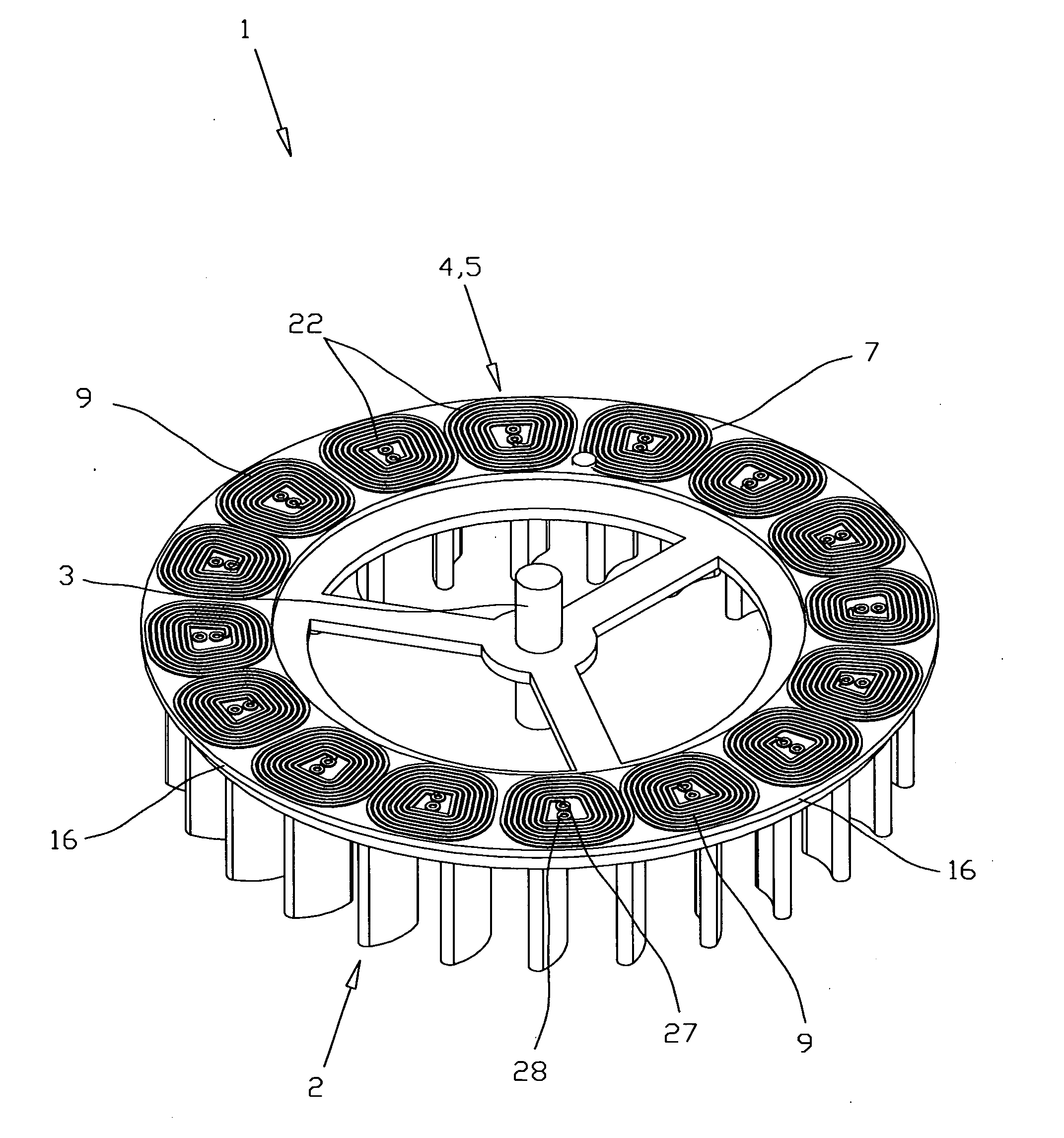
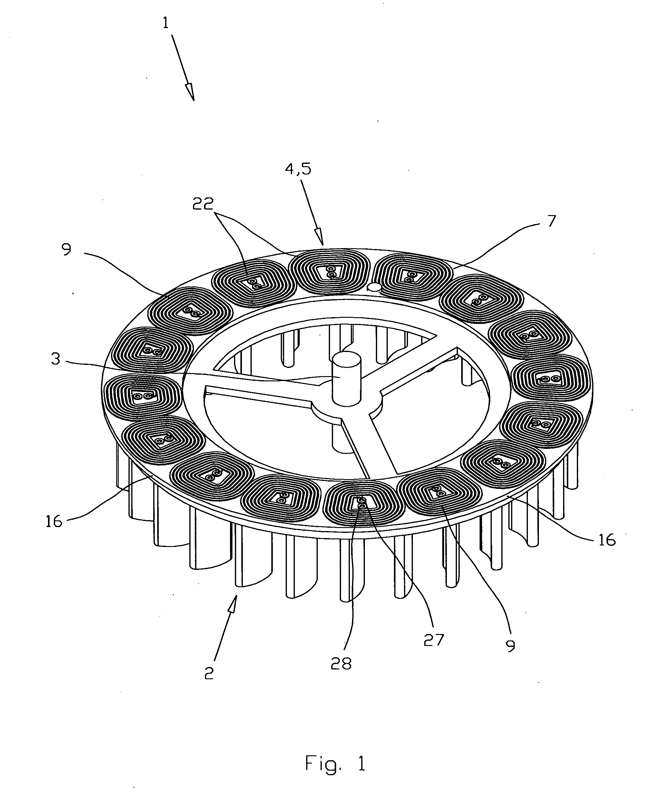
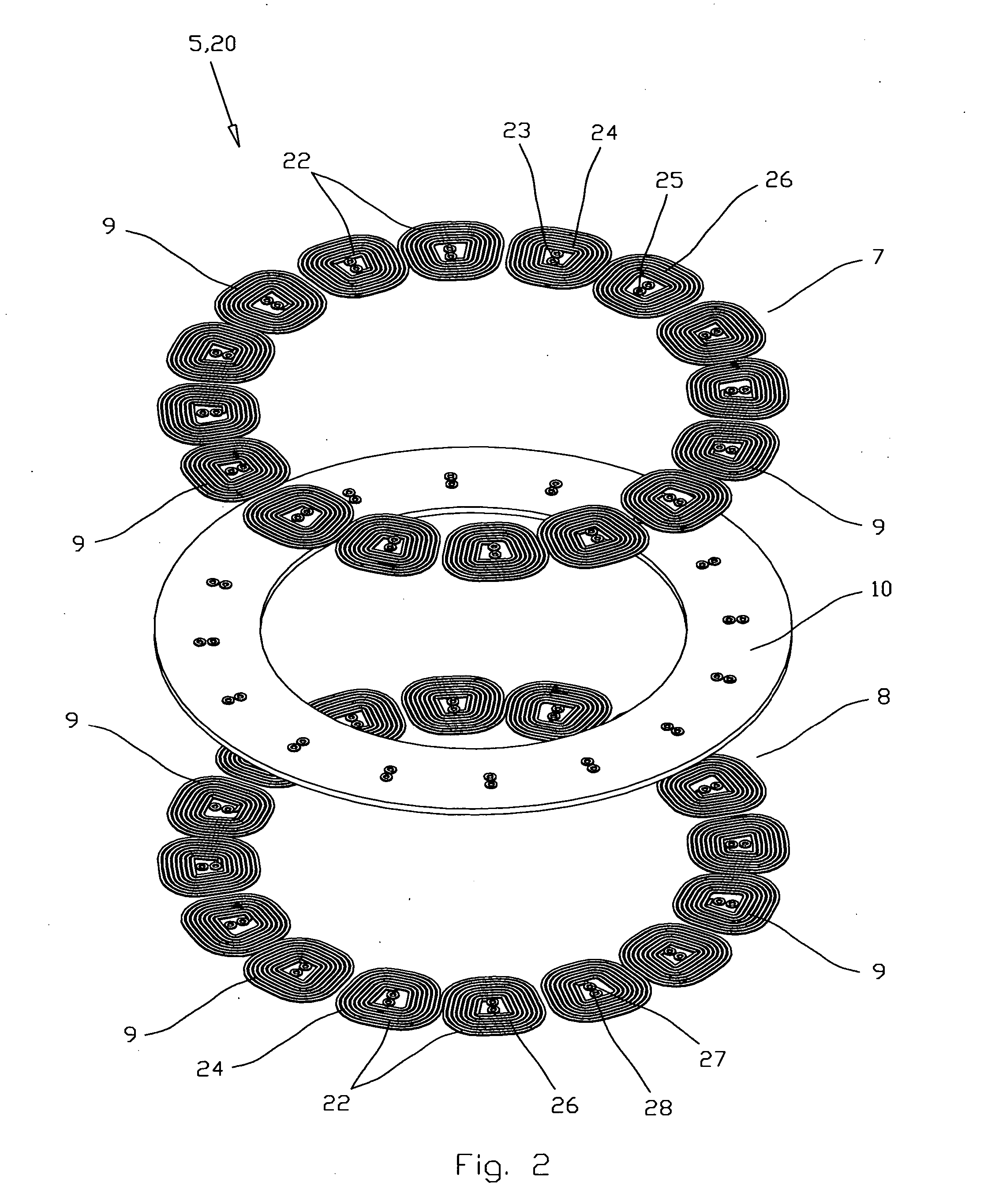
[0040] In FIGS. 1-6, an electric drive 1 comprises a magnetic rotor 2 with an axis of rotation 3 and a stator 4 having two ring-shaped windings 5 and 6. Each of said windings 5 and 6 comprises two coil layers: winding 5 has electrically connected coil layers 7 and 8 with plurality of circumferentially-arrayed printed coils 9 located around said axis 3 and a layer of electro-insulating material 10 between layers 7 and 8. Winding 6 has electrically connected coil layers 11 and 12 with plurality of circumferentially arrayed printed coils 13 located around said axis 3 and a layer of electro-insulating material 14 between coil layers 11 and 12. Windings 5 and 6 are located in such a way that two coil layers 8 and 11 belonging to the different windings, accordingly 5 and 6, are separated only by an additional layer 15 of electro-insul...


PUM


Abstract

An electric drive comprising a stator with at least two ring-shaped windings and controllers, and a magnetized rotor with an axis of rotation. Each of said windings comprises at least one coil layer with circumferentially arrayed coils located around said axis, and a layer of electro-insulating material, and each winding is electrically connected to a power source through an individual controller. At least two said windings are electrically connected by their controllers in parallel, with the possibility to function jointly and/or independently. At least two nearest windings are located in such a way that two said coil layers belonging to the different windings are separated by an additional layer of electro-insulating material. The coils of said nearest coil layers of different windings are made the same in transparent view, so that the distances between corresponding parts of said coils of said nearest windings are equal to the thickness of said additional layer of an electro-insulating material. At least two said nearest windings are made as parts of a common multi-layer printed circuit board.

Description

CROSS-REFERENCE TO RELATED APPLICATIONS [0001] The present application claims the benefit of priority of U.S. Provisional Patent Application No. 60 / 503,441 for Edward Lopatinsky et al., the entire content of which is incorporated herein by reference.BACKGROUND OF THE INVENTION [0002] The present invention relates generally to electric drives and is useful in direct current brushless motors. [0003] It is desirable to have small overall dimensions and high reliability in electric drives. These requirements are especially important for electric drives operating in cooling systems with blower and heatsink for regulating the temperature of electronic devices. The trend toward smaller and thinner electronic devices having faster processors renders traditional heat removal cooling systems inadequate. It is desirable that the electric drives of these systems be small, thin and efficient as well. [0004] At the same time the electric drives should have high reliability, since the failure of t...

Claims


Application Information

Patent Timeline
Patent Type & Authority Applications(United States)
IPC IPC(8): F04D25/06H02K3/26H02K3/28H02K7/14H02K11/04H02K16/00H02K21/24
CPCF04D25/066H02K3/26H02K3/28H02K21/24H02K11/0073H02K16/00H02K7/14H02K11/33F04D25/0653
Inventor LOPATINSKY, EDWARDFEDOSEYEV, LEVROSENFELD, SAVELIYSCHAEFER, DANIEL
Owner ROTYS
Why Eureka
Try Eureka