
Flow-cytometry-based hematology system

a flow-cytometry and hematology technology, applied in the field of bioparticle analysis, can solve the problems of reducing the production of red blood cells, unable to keep up with red cell removal, and low overall red blood cell count and hematocrit, so as to reduce system and operational costs, reduce reagent waste, and be reliable.

Inactive Publication Date: 2006-09-14
IDEXX LABORATORIES
View PDF65 Cites 68 Cited by
  • Summary
  • Abstract
  • Description
  • Claims
  • Application Information

AI Technical Summary

Benefits of technology

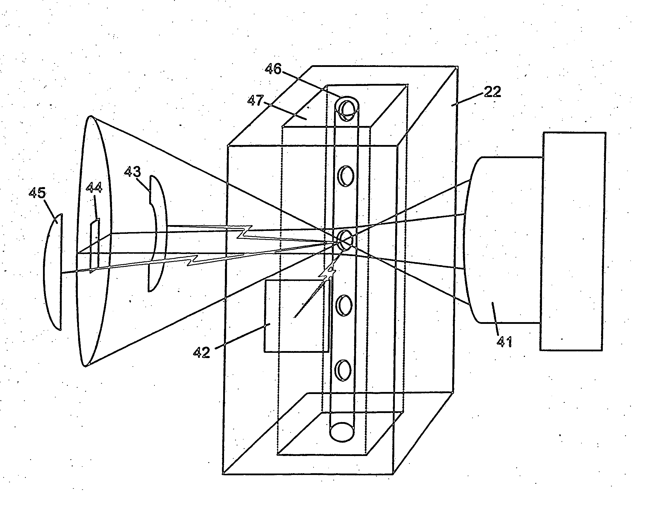
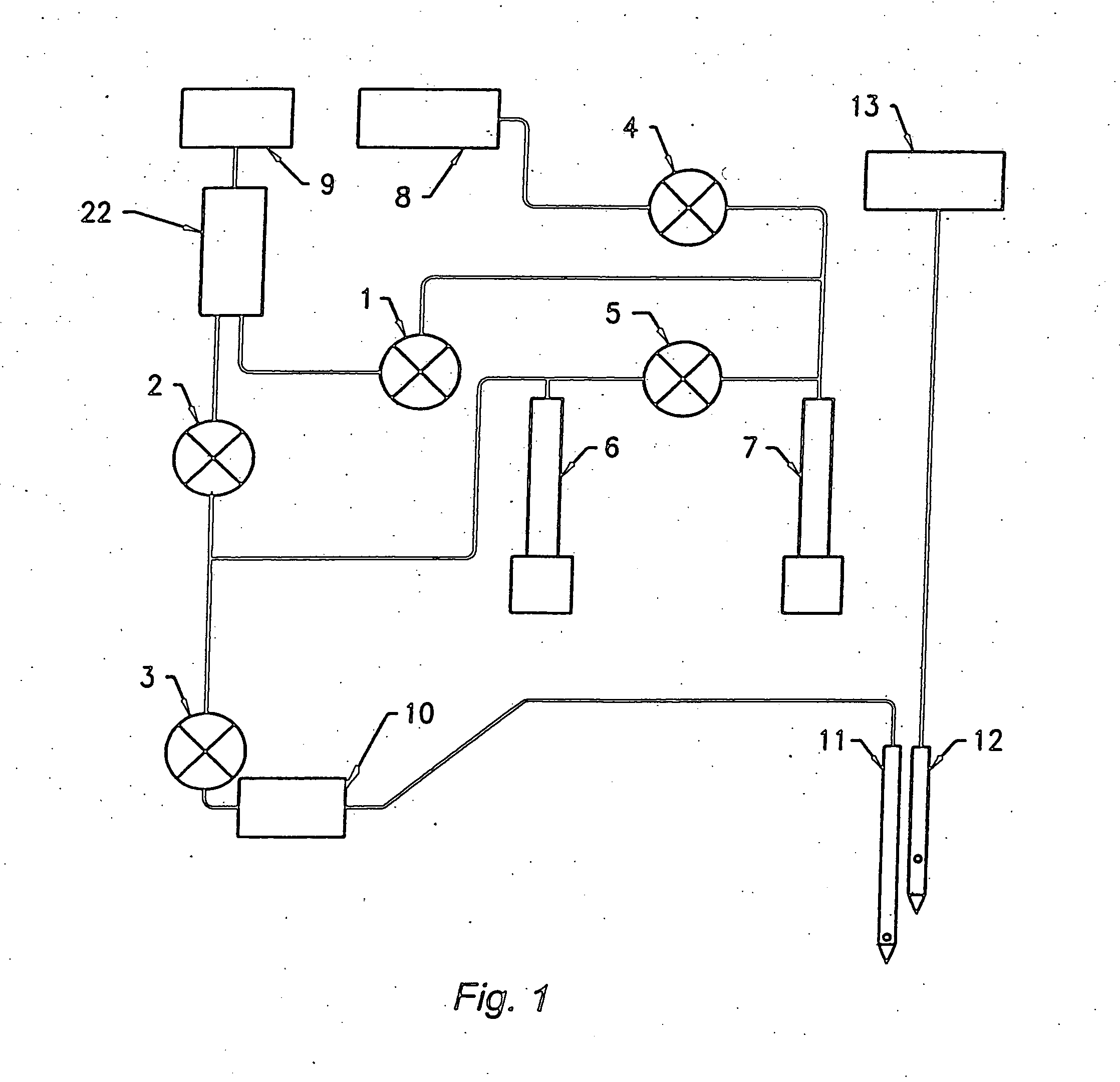
[0047] The device of the present invention is a flow-cytometry based bioparticle analysis system that combines unconventional flow cytometry light scatter measurement techniques with a unique approach to reagent delivery and sample processing that minimizes reagent waste and reduces systems and operational costs. More particularly, the present invention is directed to a flow cytometry-based hematology system that employs a set of selected features which, in combination, provide at least a complete blood count, a five-part differential white blood cell count, and a reticulocyte count in a system that is small, reliable, and inexpensive enough to be well suited for use in small clinical laboratories, doctor's offices, veterinarian offices, and the like. The system may be used in the analysis of whole blood samples, or in blood-derived samples, such as, for example, platelet-rich plasma, packed red blood cells, and the like. The system may also be used in the analysis of any biological sample other than blood or blood-derived products (e.g., urine) that is amenable to analysis by standard flow cytometry techniques. The present invention also relates to methods for use of the flow cytometry-based blood sample analysis system.
[0048] This present invention is a flow cytometry-based hematology system that includes a lensless optical detection system for collection of light emitted from a laser light source, after interacting with a cell or particle. The use of a photodetector array that collects multiple light measurements without the need for any moving parts, lenses or other types of optical components greatly increases the reliability of the system. The photodetector array is preferably such that various types of scattered light are detectable, and the data collected provides a complete hematological analysis when used in combination with a high numerical aperture technique for right angle scatter. The laser light source may be a standard diode laser light source that is shaped to produce a thin line, as disclosed in U.S. Pat. No. 6,612,719. The diode laser reduces the size and complexity of the system. Mode-hopping, a problem that occurs with diode lasers, may be reduced significantly by the application of a high-frequency modulation technique. Finally, the system preferably uses a unique system of consumable reagent tubes that act as disposable reaction chambers, mixing chambers, and waste chambers for the blood sample analyses. The consumable tubes incorporate polystyrene latex particles or the like (i.e., fixed cells,), which act as internal standards to ensure that the dilutions made during processing of the samples have been carried out correctly. The use of these consumable tubes results in less waste, greater reliability, and greatly improved accuracy and validation of the results.
[0050] It is another object of the present invention to provide a lensless light detection system that comprises a photodetector array on an integrated circuit chip which is effective to measure at least one of axial light loss, low-angle forward scattered light, and high-angle forward scattered light.
[0051] It is another object of the present invention to provide a lensless light detection system that comprises a photodetector array, arranged on a plurality of electrically distinct integrated circuit chips, which is effective to measure at least one of axial light loss, low-angle forward scattered light, and high-angle forward scattered light.

Problems solved by technology

In anemia, red cell production may be diminished to the point where it can no longer keep up with red cell removal, and as a result the overall red blood cell count and hematocrit are low.
If few or no reticulocytes are detectable in these patients, the bone marrow is not adequately responding to the red blood cell deficit.
Like RBCs, platelets lack nuclei and thus cannot reproduce.
However, the skills necessary to perform these test manually are rare and require years of training.
Furthermore, the time required to perform each of these tests manually is very high.
However, these systems were unable to distinguish among all the different types of white blood cells, and thus were unable to provide a five-part differential count.
Furthermore, these instruments were also unable to distinguish between reticulocytes and normal red blood cells, and thus could also not provide a reticulocyte count.
However, unless two separate dilutions of the same sample are performed, the method requires large volumes of sample to provide sufficient statistical data with regard to the less common blood components.
For example, material within cells having a strong absorption at the illuminating wavelength may interfere with size determination because cells containing this material produce smaller forward scatter signals than would otherwise be expected, leading to an underestimate of cell size.
However, the calibration procedures are lengthy and complicated, and require extensive training to perform properly.
Changes in the instrument or in the sample may alter the performance of the instrument.
However, these early systems did not perform a CBC or white blood cell differential.
However, these instruments require complex and expensive optical systems to make such measurements.
This combination of multiple sample hydraulic paths creates an undesirably high level of complexity, due to the requirement for large numbers of valves, vacuum lines, reaction chambers, syringes, vacuum pumps, miniature orifices, and the like.
In addition, a significant amount of training is required to learn how to use these instruments properly.
Furthermore, these instrument systems require service several times a year, at a minimum.
As a result, the high costs associated with purchasing, operating and maintaining these high-end instruments make them financially inaccessible to small clinics and doctor's offices.
Doctors can obtain limited access to these instruments by contracting with commercial laboratories that will pick up blood samples from the clinic or doctor's office and transport the samples back to the laboratory for analysis on these high-end hematology systems.
This process is very time-consuming, and usually the doctor will not have the results until the following day, at the earliest.
Instrumentation, such as impedance counters that perform CBC with limited WBC differentials, are available for these in-clinic laboratories, but systems that can produce five-part differentials and reticulocyte counts are not.
These manual methods, however, are slow, labor-intensive, and prone to operator error.
While the high-end hematology systems advanced by incorporating flow cytometric techniques and other improvements, the technology used in the low-end systems has changed very little.
These low-end instruments have become much more compact and efficient through incorporation of semiconductor microelectronics where applicable; however, in the end, these systems are functionally no different from the impedance counters used by clinical laboratories in the late 1970's and early 1980's.
In particular, these instruments still cannot perform a five-part WBC differential, nor can they produce a reticulocyte count.
Since the number of samples run on these instruments is low compared to their laboratory counterparts, significant volumes of reagents are wasted in performing startup and shutdown cycles, as well as in system cleanings between samples.
Thus, it is impossible to predict how many patient samples a user will get from a reagent pack.
As a result, the user must maintain an excess amount of reagents on hand, leading inevitably to a substantial degree of reagent waste.
In addition, the hydraulics of these instruments, though generally less complex than the high-end laboratory systems, are still prone to the same reliability issues associated with the use of high numbers of vacuum lines, valves, and vacuum pumps, as well as with the small dimensions of the apertures used to count cells.
Thus, for in-clinic and in-office applications, such low-end impedance instruments are severely deficient in producing the results needed for complete hematology analyses, are inefficient in their use of reagents, and have the same inherent reliability problems that are associated with high-end biological fluid analysis systems.
Some attempts have been made to address the clinical blood sample analysis needs of small laboratories and doctor's offices, but these efforts have met with only limited success.
While the QBC® technology addresses concerns of reliability and reagent waste for the in-clinic user, it falls well short of delivering the required parameters for a CBC, produces an incomplete differential, and does not quantify reticulocytes.
Additionally, the precision and accuracy of the parameters produced by the QBC® system, except for hematocrit, are worse than those of the low-end impedance systems.
The gas lasers conventionally employed in flow cytometer-based hematology systems produce strong light signals, but high levels of noise associated with these lasers have minimized their utility for use in flow cytometry-based hematology systems.
However, this results in greater cost for the system.
However, the optical characteristics of laser diodes are not as desirable as those of gas lasers.
When mode hops are occurring, the S / N ratio of the light measurement is very low, making it useless for measuring small particles (i.e., platelets), or to distinguish subtle difference in larger ones.
Laborious effort is required to characterize each individual laser diode to find the ideal temperature and current settings.
Furthermore, even if the ideal external temperature is determined, maintaining a constant temperature is complicated by the significant amount of heat produced when the diode laser is first turned on.
As a result, temperature equilibrium of the diode laser can take up to 30 minutes to establish, even if the diode laser and temperature control system are working properly.
This equilibration time decreases the useful life of the laser.
Lastly, the implementation of temperature control severely limits the operating temperatures at which a unit can be used, and adds significant cost and size to a relatively inexpensive and small laser diode.
Significant costs and complexity in the optics system of flow cytometry-based hematology instruments are associated with the light beam shaping optics and the light collection optics.
However, this approach reduces power density at the interrogation point in the flow cell.
Significant costs are incurred by the need to incorporate many expensive optical components.
In addition to the high cost of each of these components, each optical component also must be held securely in space, and carefully aligned in three-dimensional space with the other components of the optic system.
These steps add additional complexity and cost to the overall design.
Light collection optic systems in flow cytometry-based hematology systems are even more complex than the light beam shaping optics.
As in the beam shaping case, significant costs are incurred by the requirement for numerous optical components, each of which needs to be held in space and carefully aligned.
The sheer number of components involved in the conventional hematology systems add greatly to the cost, and reduce the reliability, of such devices.

Method used


Image

  • Flow-cytometry-based hematology system
  • Flow-cytometry-based hematology system
  • Flow-cytometry-based hematology system

Examples


example

[0216] The following description describes the system of the present invention in relation to the accompanying figures, and its use in measurement of a whole blood sample for a CBC, a five-part WBC differential, and a reticulocyte count. It will be understood by those of skill in the art that certain modifications may be made in the invention as described below without departing from the scope or spirit of the attached claims. Throughout this specification, the term “inlet side” refers to the side where a fluid enters. “Outlet side” refers to a side where fluid exits. “Sample mixture” refers to a fluid sample, usually a blood sample or blood-derived sample, that is mixed with another solution.

[0217] Referring now to FIGS. 1-9, the user initiates the process by opening a door of the system, to expose four open tube slots in a carriage 70 (slots A-D in FIG. 7). In one slot (i.e., slots A or B of FIG. 7), the user places a consumable tube 60, and in a second slot, a whole blood sample...


PUM

PropertyMeasurementUnit
thicknessaaaaaaaaaa
diameteraaaaaaaaaa
diameteraaaaaaaaaa

Abstract

A hydraulic system for a flow cytometry having a reservoir for a sheath solution, at least one syringe connected to the reservoir, the at least one syringe being driven by a motor, a single HGB module connected on an inlet side to a sample inlet which is connected to the flow cell by a single flow path passing through the HGB module, a single flow cell connected to the HGB module and at least one syringe on an inlet side of the flow cell, and to a waste container on an outlet side of said flow cell.

Description

[0001] The present application is a division of U.S. application Ser. No. 10 / 159,944 filed May 31, 2002; which is a division of U.S. application Ser. No. 09 / 715,593 filed Nov. 17, 2000; which claims the benefit of U.S. Provisional Patent Application No. 60 / 208,849, filed on Jun. 2, 2000, the entirety of each of these applications are hereby incorporated by reference.FIELD OF THE INVENTION [0002] This invention relates in general to bioparticle analysis, and more specifically to flow-cytometry-based methods and devices for performing automated blood cell analysis. BACKGROUND OF THE INVENTION [0003] Mammalian peripheral blood usually contains three major classifications of blood cells—red blood cells (“RBCs”), white blood cells (“WBCs”), and platelets (“PLTs”). These cells are suspended in a solution referred to as plasma, which contains many different proteins, enzymes and ions. The functions of the plasma components include blood coagulation, osmolality maintenance, immune surveilla...

Claims


Application Information

Patent Timeline
Patent Type & Authority Applications(United States)
IPC IPC(8): G01N33/48G01N1/10G01N15/14G01N21/05G01N21/53G01N33/49G01N33/72H04L25/06
CPCG01N1/38G01N15/1434G01N15/1459G01N15/147G01N35/1095G01N2015/0069G01N2015/0076G01N2015/008G01N2015/0084G01N2015/1486G01N2015/1493H04L25/063
Inventor ROCHE, JOHN W.FLYNN, HAROLD C. JR.RUSSELL, JAMES W.
Owner IDEXX LABORATORIES
Learn More