Refrigerating system

a technology of refrigerating system and refrigeration component, which is applied in the direction of refrigeration components, mechanical equipment, lighting and heating equipment, etc., to achieve the effect of enhancing system reliability, enhancing system reliability, and enhancing system reliability

Inactive Publication Date: 2002-06-18
DAIKIN IND LTD
View PDF8 Cites 73 Cited by
  • Summary
  • Abstract
  • Description
  • Claims
  • Application Information

AI Technical Summary

Benefits of technology

According to the seventh invention, even if the temperature of the discharge gas of the low stage side compressor has excessively increased, the low stage side compressor can be protected thereby enhancing system reliability.
According to the eighth invention, even if the temperature of the discharge gas of the high stage side compressor has excessively increased, the high stage side compressor can be protected thereby enhancing system reliability.
According to the ninth invention, since liquid back of the high stage side compressor can be obviated even in a transient operating state or under severe service conditions, this enhances system reliability.
According to the tenth invention, since the amount of change of opening of the motor-operated expansion valve is changed according to the opening, this prevents the motor-operated expansion valve from being excessively opened and closed resulting in facilitating implementation of stable control.
According to the eleventh invention, since the opening change of the motor-operated expansion valve is made relatively slowly for control in its opening direction or made relatively rapidly for control in its closing direction, this prevents excessive liquid storage into the accumulator resulting in facilitating implementation of stable control.

Problems solved by technology

Accordingly, there has been a problem in the conventional binary refrigerating system in that even if the low stage side compressor (207) is started up behind a certain period, the temperature-sensitive expansion valve (205) cannot response to an abrupt increase in load resulting in operation of the protective device of the low stage side refrigerant circuit (202).

Method used


Image

  • Refrigerating system
  • Refrigerating system
  • Refrigerating system

Examples


first embodiment

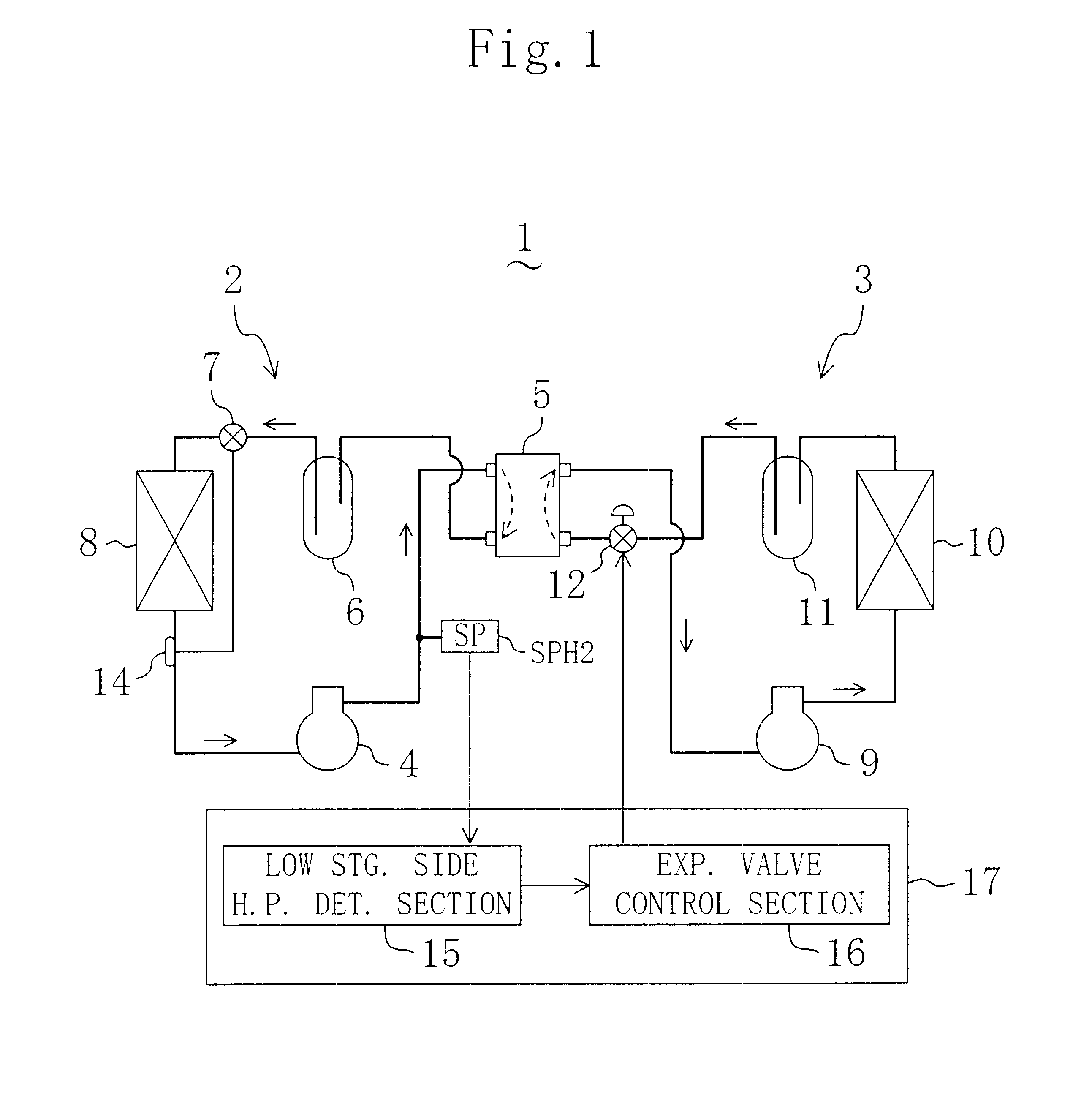
As shown in FIG. 1, a refrigerating system (1) according to a first embodiment is a so-called binary refrigerating system provided in a cold storage, and includes a low stage side refrigerant circuit (2) and a high stage side refrigerant circuit (3).

The low stage side refrigerant circuit (2) is formed by connecting a low stage side compressor (4), a cascade condenser (5) as a refrigerant heat exchanger, a low stage side receiver (6), a low stage side expansion valve (7) and an evaporator (8) for cooling the in-storage air in this order. The low stage side expansion valve (7) is constituted by a temperature-sensitive expansion valve. A temperature sensing bulb (14) connected to the low stage side expansion valve (7) is fixed to part of a refrigerant pipe located between the evaporator (8) and the low stage side compressor (4) and in the vicinity of the evaporator (8). The cascade condenser (5) is constituted by a plate-type heat exchanger formed by laminating a large number of heat-t...

second embodiment

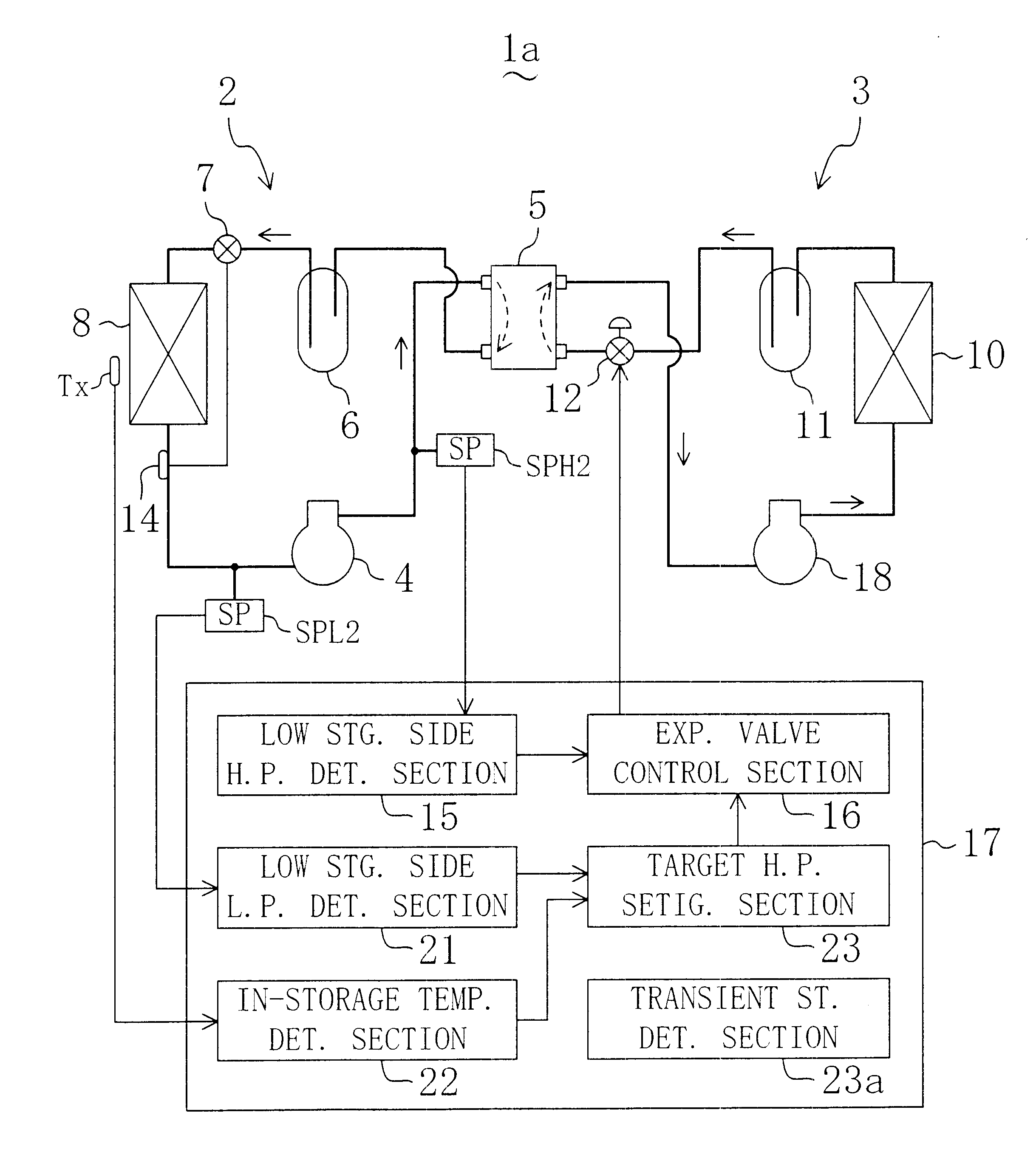
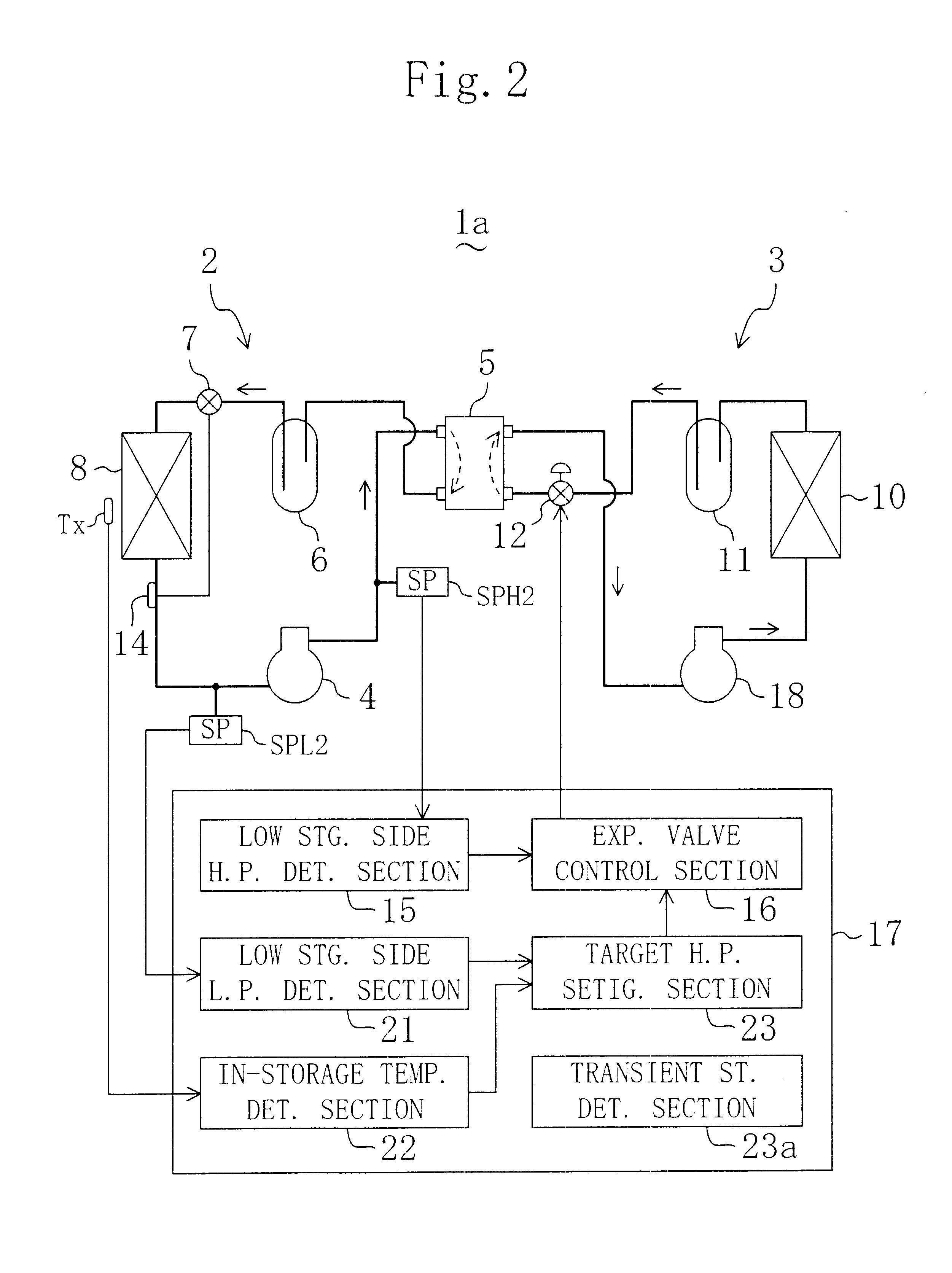
As shown in FIG. 2, a refrigerating system (1a) according to a second embodiment is formed by adding the following changes to the refrigerating system (1) of the first embodiment. Like parts as in the refrigerating system (1) of the first embodiment are identified by similar reference characters and description thereof will be omitted.

In this refrigerating system (1a), the high stage side compressor (18) of the high stage side refrigerant circuit (3) is constituted by a compressor capable of free capacity control, for example, by an inverter-controlled compressor. At the suction side of the low stage side compressor (18) of the low stage side refrigerant circuit (2), a low-pressure sensor (SPL2) is provided as a low-pressure sensing means for sensing the low pressure. Further, in the storage, a temperature sensor (Tx) is placed as a temperature sensing means for sensing the in-storage air temperature.

The controller (17) includes, in addition to the low stage side high pressure detec...

third embodiment

A refrigerating system (1b) according to a third embodiment shown in FIG. 6 is also formed by adding some changes to the refrigerating system (1) of the first embodiment. Like parts as in the first embodiment are identified by similar reference characters and description thereof will be omitted.

In this refrigerating system (1b), the high stage side compressor (18) of the high stage side refrigerant circuit (3) is constituted by a compressor capable of free capacity control. In the storage, a temperature sensor (Tx) is placed for sensing the in-storage air temperature. In the pipe located on the suction side of the high stage side compressor (18) of the high stage side refrigerant circuit (3), a low-pressure sensor (SPL1) is provided as a low-pressure sensing means for sensing the low pressure in the high stage side refrigerant circuit (3). An accumulator (24) is provided between the cascade condenser (5) and the high stage side compressor (18). In the pipe between the cascade conden...


PUM


Abstract

The refrigerating system includes a low stage side refrigerant circuit (2) formed by connecting a low stage side compressor (4), a cascade condenser (5), a low stage side receiver (6), a low stage side expansion valve (7) formed of a temperature-sensitive expansion valve and an evaporator (8) in this order. The system also includes a high stage side refrigerant circuit (3) formed by connecting a high stage side compressor (9), a condenser (10), a high stage side receiver (11), a high stage side expansion valve (12) formed of a motor-operated expansion valve and the cascade condenser (5) in this order. The opening of the high stage side expansion valve (12) is adjusted so that the pressure sensed by a high-pressure sensor (SPH2) for sensing the high pressure in the low stage side refrigerant circuit (2) reaches a predetermined target high pressure.

Description

The present invention relates to a refrigerating system, and particularly relates to a binary refrigerating system including a low stage side refrigerant circuit and a high stage side refrigerant circuit.A binary refrigerating system has been conventionally used as a refrigerating system for a cold storage, a thermal-shock testing system or the like. The binary refrigerating system is constituted by a low stage side refrigerant circuit and a high stage side refrigerant circuit which are connected to each other through a cascade condenser as disclosed in Japanese Unexamined Patent Publication Gazette No. 9-210515.With reference to FIG. 13, the conventional binary refrigerating system (200) will be now described. The low stage side refrigerant circuit (202) is formed by connecting a low stage side compressor (207), a cascade condenser (206), a low stage side receiver (208), a low stage side expansion valve (204) and an evaporator (209) in this order, while the high stage side refriger...

Claims


Application Information

Patent Timeline
Patent Type & Authority Patents(United States)
IPC IPC(8): F25B7/00F25B13/00F25B49/02F25B1/00
CPCF25B7/00F25B13/00F25B49/027Y02B30/741F25B2600/021F25B2600/21Y02B30/72F25B2341/065Y02B30/70F25B41/34
Inventor KAWAKATU, NORIYASUUENO, AKITOSHIMUKAIDANI, TOSHIAKIUENO, TAKEO
Owner DAIKIN IND LTD
Why Eureka
Try Eureka