Electronically phase-locked laser systems

a laser system and phase lock technology, applied in semiconductor lasers, laser details, electrical equipment, etc., can solve the problems of thermal non-uniformities such as filamentation producing spatially and spectral multi-mode outputs, poor beam quality of semiconductor diode lasers above 1 watt, and affecting the performance of lasers. achieve high optical output power levels, limited beam quality, and high electrical efficiency

Active Publication Date: 2010-12-07
INTEL CORP
View PDF2 Cites 42 Cited by
  • Summary
  • Abstract
  • Description
  • Claims
  • Application Information

AI Technical Summary

Benefits of technology

[0012]A multiplicity of phase-locked semiconductor lasers which seed single frequency fiber amplifiers and are under electronic phase-control enables the efficient combination of fiber-amplified outputs. Such electronic control of optical phase enables laser system scalability to high optical output power levels while providing high electrical efficiency, diffraction limited beam quality, wavefront control and potentially narrow spectral linewidth.

Problems solved by technology

One limitation of the latter application, however, is that as the optical power of semiconductor diode lasers and fiber lasers increases, several factors begin to degrade the spectral and spatial quality of the optical output beam.
For example, thermal non-uniformities such as filamentation produce spatially and spectrally multi-moded outputs with poor beam quality for semiconductor diode lasers above ˜1 Watt.
Each of these factors can seriously degrade the optical performance of typical implementations of a high power laser.
Therefore, for applications requiring near-diffraction limited beams with good focusability and low divergence, it challenging to exploit the advantages of diode laser-based systems and scale their power beyond 1 KW.
Above this threshold, several negative factors conspire to degrade or limit laser performance.
This scalability is impacted, for example, by design tradeoffs resulting from heat extraction requirements as well as optical nonlinearities and non-idealities.
Practical issues such as alignment tolerances, reliability, electrical efficiency, cost, size and weight are also key factors influencing the successful realization of high power laser systems.

Method used


Image

  • Electronically phase-locked laser systems
  • Electronically phase-locked laser systems
  • Electronically phase-locked laser systems

Examples


example

1 MW Coherently and Spectrally Combined Laser

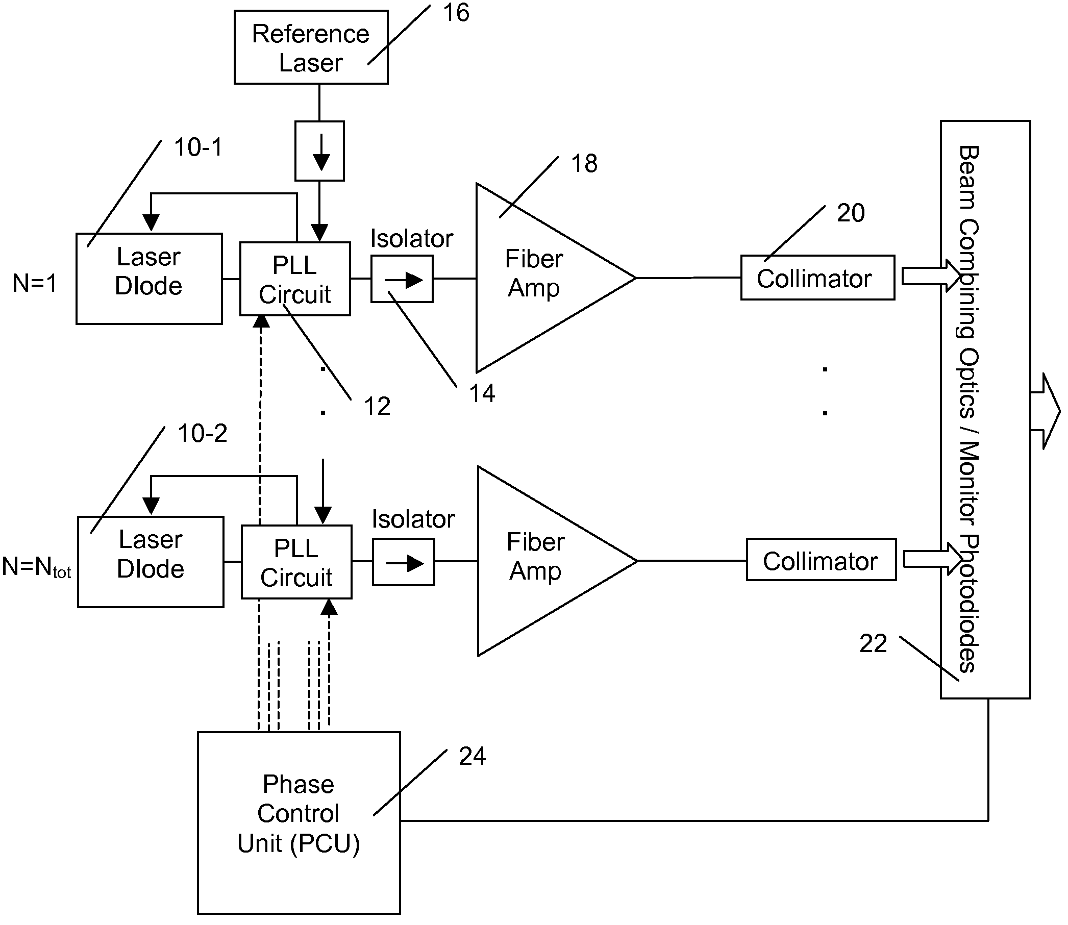
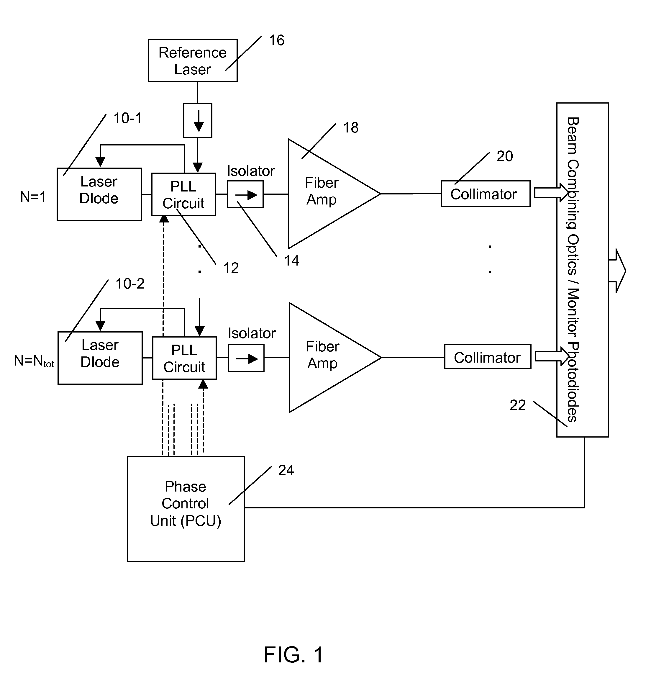
[0073]In an alternate example, ten high power laser modules, each producing 100 KW at 10 unique wavelengths, are spectrally combined. The module consists, for example, of an array of 217 phase-locked laser diodes 10, which are used to seed 500 W, single mode, single polarization, single frequency amplifiers 18. Each module is spaced in wavelength by 1 to 0.01 nm and combined by a free space wavelength beam combiner utilizing dielectric thin film filters, volume Bragg gratings, unbalanced interferometers / interleavers or planar diffraction gratings.

[0074]In conclusion, the semiconductor laser phase-locking techniques herein provide several advantages, including the realization of various high power, electronically phase-locked laser systems with improved scaleability, reduced complexity and improved performance, as well as electronic linewidth narrowing of laser diodes. These applications are the consequence of the techniques disclosed here...


PUM


Abstract

Semiconductor diode lasers are phase-locked by direct current injection and combined to form a single coherent output beam. The optical power is amplified by use of fiber amplifiers. Electronically control of the optical phases of each emitter enables power efficient combining of output beams to be maintained under dynamic conditions.

Description

REFERENCE TO RELATED APPLICATIONS[0001]This application relies for priority on provisional application 60 / 897,742, filed on Jan. 26, 2007 and entitled “Electronically phase-locked high power laser utilizing semiconductor laser elements”.FIELD OF THE INVENTION[0002]This invention relates to semiconductor laser systems; in particular, to laser systems comprised of semiconductor laser diodes that are electronically phase-locked to an optical reference.BACKGROUND OF THE INVENTION[0003]Techniques to control the amplitude and phase of semiconductor laser diodes promise to extend the performance of laser diode systems and thereby enable a wide range of new applications. Presently, semiconductor lasers exhibit several favorable attributes, including low cost, small size and high electrical efficiency, which have made them key elements in communications systems and high power laser systems (e.g., for pumping fiber lasers). One limitation of the latter application, however, is that as the opt...

Claims


Application Information

Patent Timeline
Patent Type & Authority Patents(United States)
IPC IPC(8): H01S3/13
CPCH01S3/2308H01S3/2383H01S5/042H01S3/06754H01S3/10053H01S3/1618H01S5/06821H01S5/4025
Inventor KEWITSCH, ANTHONY S.RAKULJIC, GEORGE A.
Owner INTEL CORP
Why Eureka
Try Eureka