Pre-curved cochlear implant electrode array

a cochlear implant and electrode array technology, applied in the direction of external electrodes, head electrodes, ear treatment, etc., can solve the problems of conductive hearing loss, impeded normal mechanical pathways for sound to reach the hair cells in the cochlea, and deafness sensorineural hearing loss

Inactive Publication Date: 2009-02-12
COCHLEAR LIMITED
View PDF36 Cites 13 Cited by
  • Summary
  • Abstract
  • Description
  • Claims
  • Application Information

AI Technical Summary

Benefits of technology

[0038]The outer surface of the second layer of the carrier is preferably smooth to prevent any damage to the cochlea as the carrier is inserted into the cochlea.
[0047]The carrier can also include a tip member, the tip member being straighter than the rest of the elongate carrier. The tip member is also preferably more flexible than the remainder of the stylet. In a further embodiment, the stylet can have a variable stiffness.
[0054]Each fluid egress means preferably has a valve means that allows fluid to exit the lumen but prevents, or at least substantially prevents, fluid flow from external the elongate member back into the lumen within the carrier.
[0058]In one embodiment, the bioactive substance can comprise a steroid. In another embodiment, the bioactive substance can perform a function of reducing the resting neuron potential of neurons within the cochlea. The use of such substances can result in less energy being required to excite the neurons and cause stimulation.

Problems solved by technology

Of these types, conductive hearing loss occurs where the normal mechanical pathways for sound to reach the hair cells in the cochlea are impeded, for example, by damage to the ossicles.
In many people who are profoundly deaf, however, the reason for deafness is sensorineural hearing loss.
These people are thus unable to derive suitable benefit from conventional hearing aid systems, because there is damage to or absence of the mechanism for nerve impulses to be generated from sound in the normal manner.
Moreover, the current from each electrode may flow in all directions, and the electrical fields corresponding to adjacent electrodes may overlap, thereby causing cross-electrode interference.
This is a challenge as the array needs to be shaped such that it assumes a curved shape to conform with the shape of the modiola and must also be shaped such that the insertion process causes minimal trauma to the sensitive structures of the cochlea.

Method used


Image

  • Pre-curved cochlear implant electrode array
  • Pre-curved cochlear implant electrode array
  • Pre-curved cochlear implant electrode array

Examples


Embodiment Construction

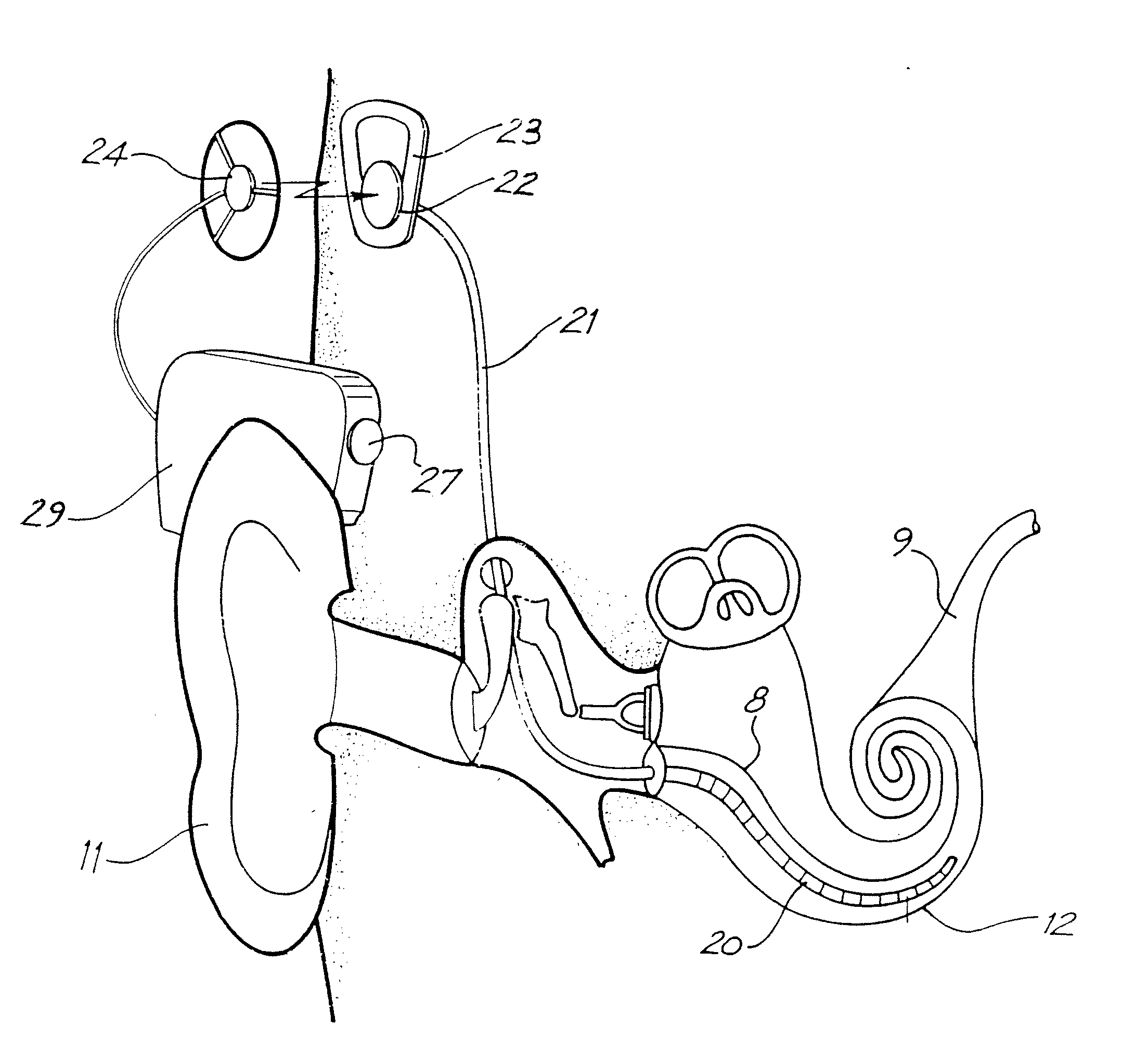
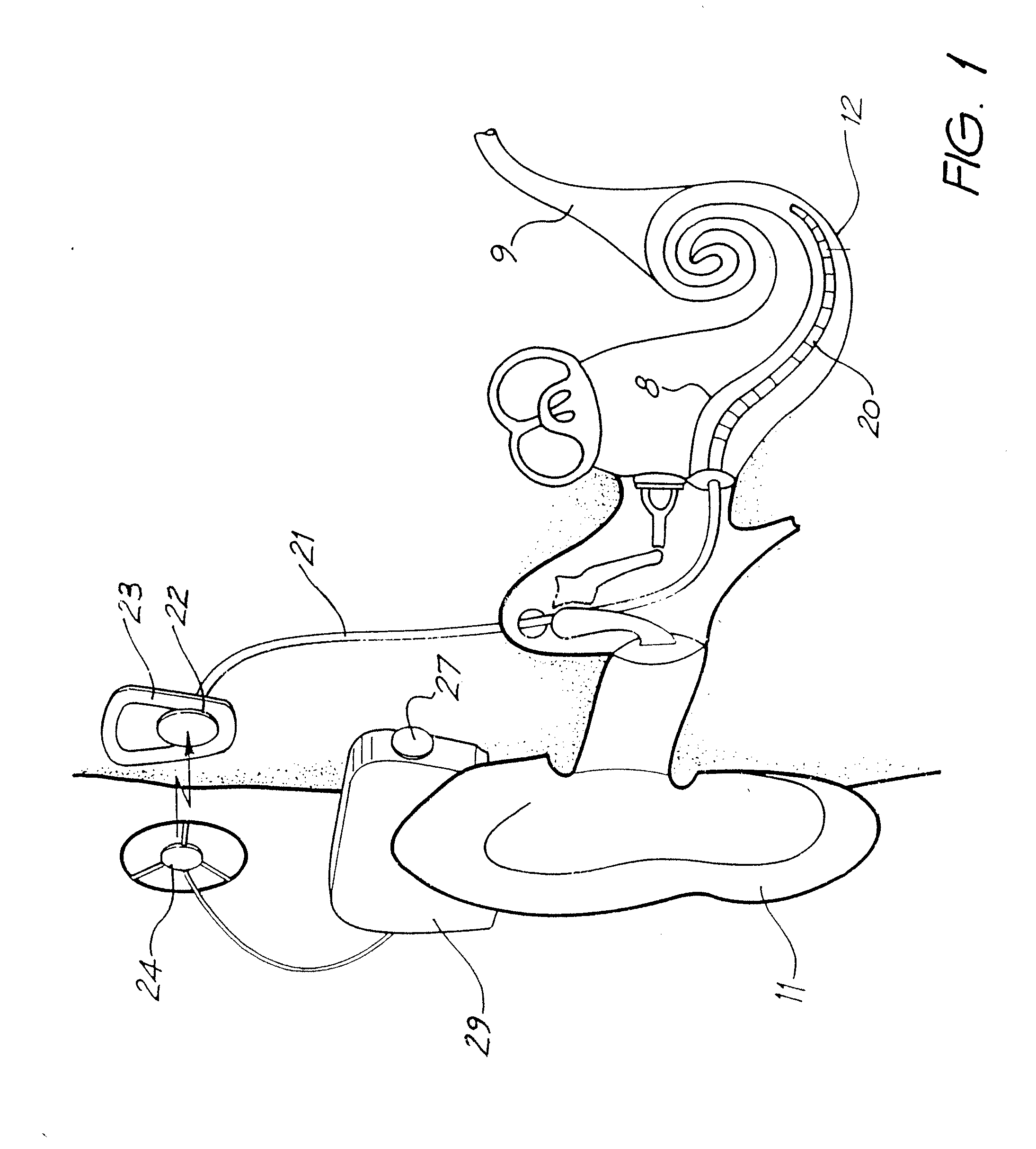
[0102]Before describing the features of the present invention, it is appropriate to briefly describe the construction of one type of known cochlear implant system with reference to FIG. 1.

[0103]Known cochlear implants typically consist of two main components, an external component including a speech processor 29, and an internal component including an implanted receiver and stimulator unit 22. The external component includes a microphone 27. The speech processor 29 is, in this illustration, constructed and arranged so that it can fit behind the outer ear 11. Alternative versions may be worn on the body. Attached to the speech processor 29 is a transmitter coil 24 which transmits electrical signals to the implanted unit 22 via a radio frequency (RF) link.

[0104]The implanted component includes a receiver coil 23 for receiving power and data from the transmitter coil 24. A cable 21 extends from the implanted receiver and stimulator unit 22 to the cochlea 12 and terminates in an electro...


PUM

PropertyMeasurementUnit
resiliently flexibleaaaaaaaaaa
biocompatibleaaaaaaaaaa
thicknessaaaaaaaaaa

Abstract

An implantable electrode array (30) that can adopt a first configuration selected to allow the array (30) to be inserted into a cochlea (12) of an implantee and at least a second configuration in which the array can apply tissue stimulation. The array (30) comprises an elongate carrier (31) having a proximal end (37), a distal end (34), and an inner surface (35) conformable with the inner wall of the implantee's cochlea (12). A plurality of electrodes (36) are supported within the carrier (31) at respective spaced locations thereon in a region between the proximal end (37) and the distal end (34) with at least one of the electrodes having a surface that is at least adjacent the inner surface (35) of the carrier (31). The carrier (31) is formed in the second configuration from a first layer (32) and at least a second layer (32) of resiliently flexible material. A method of forming an array (30) is also described.

Description

CROSS-REFERENCE TO RELATED APPLICATION(S)[0001]This application is a continuation of U.S. patent application Ser. No. 10 / 332,515, filed Jan. 9, 2003, which is a National Phase Patent Application of International Application Number PCT / AU01 / 01541, filed on Nov. 28, 2001, which in turn claims priority to Australian Patent Application Number PR 1779, filed on Nov. 29, 2000, and Australian Patent Application Number PR 1780, filed on Nov. 29, 2000.[0002]The following applications disclose subject matter that may be considered related to each other:[0003]Ser. No. 10 / 332,515, filed Jan. 9, 2003, entitled “Pre-Curved Cochlear Implant Electrode Array”.[0004]Ser. No. 10 / 473,379, filed Sep. 26, 2003, entitled “Laminated Electrode For A Cochlear Implant”.[0005]Ser. No. 10 / 471,713, filed Sep. 10, 2003, entitled “Curved Cochlear Implant Electrode Array”.FIELD OF THE INVENTION[0006]The present invention relates to an implantable device and, in particular, to an implantable cochlear electrode assem...

Claims


Application Information

Patent Timeline
Patent Type & Authority Applications(United States)
IPC IPC(8): A61N1/00A61F11/04A61F2/18A61N1/05
CPCA61F11/004B28B5/00A61N1/0541A61F11/20
Inventor GIBSON, PETERDADD, FYSHTREABA, CLAUDIUPARKER, JOHN
Owner COCHLEAR LIMITED
Why Eureka
Try Eureka