Image processing apparatus

a technology of image processing and signal processing, which is applied in the direction of television systems, instruments, selective content distribution, etc., can solve the problems of inability to display digital image data worldwide on televisions, and the requirement of a specific digital camera, so as to achieve the effect of easy setup of image signal reproduction procedures

Inactive Publication Date: 2009-02-12
CANON KK
View PDF5 Cites 11 Cited by
  • Summary
  • Abstract
  • Description
  • Claims
  • Application Information

AI Technical Summary

Benefits of technology

[0014]It is another objective of the present invention to enable the easy setup of the image signal reproduction procedure for an apparatus controlled by a remote controller.

Problems solved by technology

However, even when the order for the display of such the slides is set up, the information for this setup is not stored, and the setup must be repeated when digital image data stored on the same memory card are to be displayed by another television receiver.
That is, the display order, the display layout and the remote control method must again be set up, and this is very tiresome requirement.
As another vexing problem, since the management of the video planes of television receivers differ depending on the broadcast reception standards adopted by individual nations, the worldwide display on televisions of digital image data, such as may be obtained by a specific digital camera, is not possible.

Method used


Image

  • Image processing apparatus
  • Image processing apparatus
  • Image processing apparatus

Examples


first embodiment

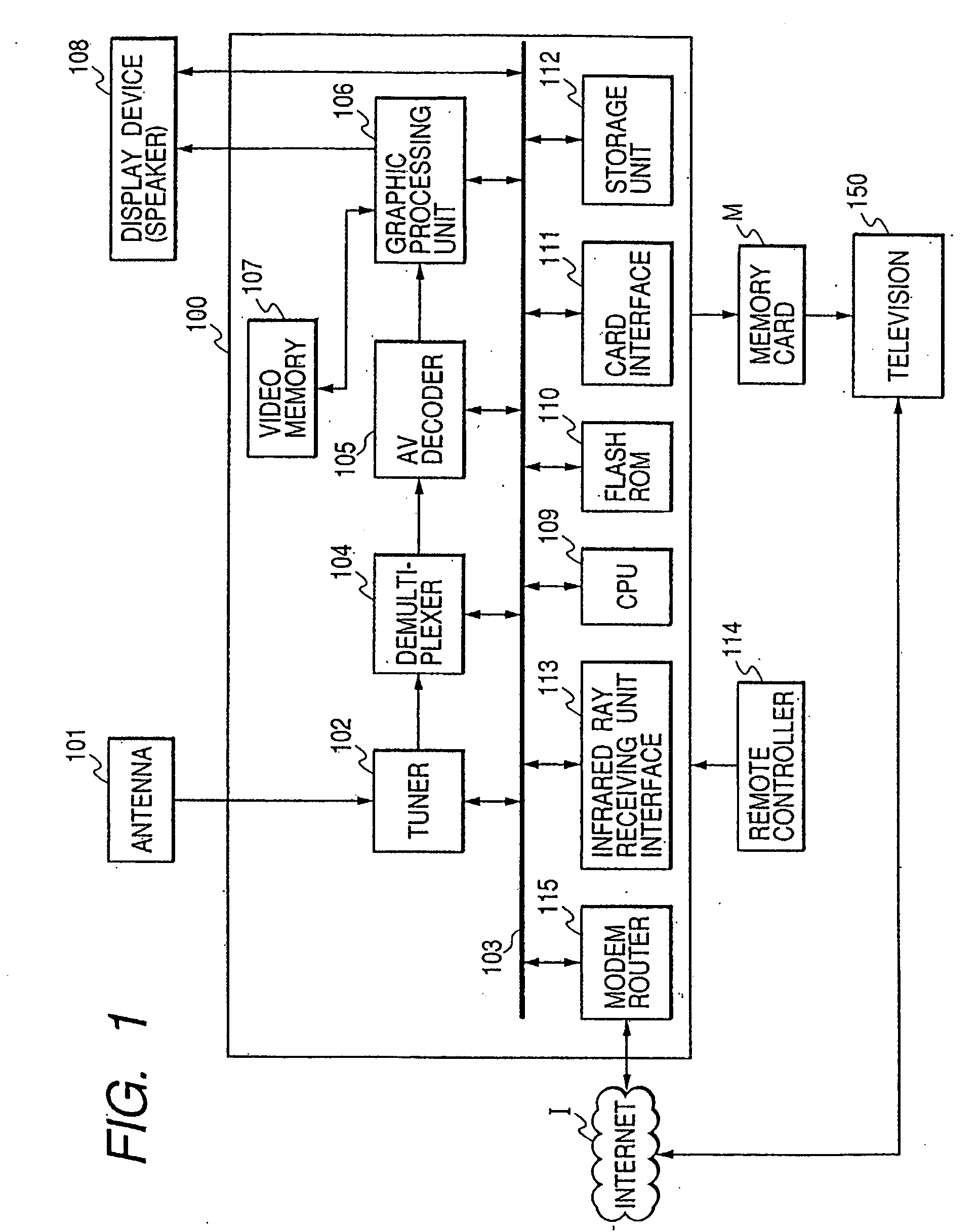
[0032]FIG. 1 is a diagram showing the configuration of a digital television system according to the present invention. In FIG. 1, digital television receivers (hereinafter referred to simply as receivers) 100 and 150 have the same configuration, and are connected across the Internet I.

[0033]Also in FIG. 1, an antenna 101 is used to receive a television signal transmitted by a broadcast satellite or by a broadcasting radio wave, such as a ground wave. A tuner 102 converts into a digital signal a television signal received at the antenna 101, demodulates modulated images and sounds, and converts obtained video and audio data into an MPEG-2 transport stream. A bus 103 is used to transfer still image data and various control data. A demultiplexer 104 separates a received transport stream into compressed video data packets, compressed audio data packets and data broadcast packets.

[0034]An AV decoder 105 decodes video signals and audio signals obtained by the demultiplexer 104. A graphic ...

second embodiment

[0089]A second embodiment will now be described.

[0090]In the first embodiment, for the reproduction of each slide, the image data read out from the memory card are decoded and the decoded image data are written into the still image plane in the video memory 107.

[0091]When all the slide display data are to be displayed using only the still image plane, however, since the entire screen can not be displayed on the display device during the period in which image data read out from the memory card are being written into the still image plane, the image display is essentially delayed.

[0092]An explanation will now be given for a method whereby such a display delay period is reduced by using multiple planes which are adopted based on the BS digital television broadcast receiver standards.

[0093]The system configuration is the same as the one shown in FIG. 1, and the setting up of reproduction procedure and the contents of the registered file and the reproduction procedure management file are...


PUM

PropertyMeasurementUnit
sizeaaaaaaaaaa
timeaaaaaaaaaa
frame frequencyaaaaaaaaaa

Abstract

A signal processing apparatus, the operation of which is controlled by a remote controller, designates procedure for reproducing an image signal stored on a recording medium; allocates a reproduction function corresponding to the designated reproduction procedure to the operating key of the remote controller; generates reproduction management data that includes operating key information indicating the operating key to which the reproduction function is allocated, and reproduction procedure information indicating the designated reproduction procedure; and writes the reproduction procedure management information to the recording medium.

Description

TECHNICAL FIELD[0001]The present invention relates to a signal processing apparatus, and more particularly to the setting up of procedure for the reproduction of image signals.BACKGROUND ART[0002]A digital broadcasting system has been developed that can transmit multiplexed digital video and audio information and data broadcasting information (including still image data), and can display data with synchronization between the video data and the audio data.[0003]For example, with the BS digital broadcasting system employed in Japan, a stream of digital video data and audio data is compressed and encoded using MPEG-2 to provide an MPEG-2 transport stream, which is transmitted as packets. Furthermore, still image data, such as advertisement data, are compressed and encoded in accordance with the JPEG standards to be formed into packets, and these packets are repetitively transmitted using the Data Carousel method.[0004]A television receiver separates the packet data into video data, aud...

Claims


Application Information

Patent Timeline
Patent Type & Authority Applications(United States)
IPC IPC(8): G06F3/00G06K19/00G09G5/02G11B20/10H04N1/21H04N1/387H04N5/00H04N5/44H04N5/445H04N5/45H04N5/76H04N5/907H04N5/91H04N5/937
CPCH04N1/00291H04N21/8153H04N5/4403H04N2005/4441H04N2201/0087H04N2201/3242H04N2201/3277H04N21/4184H04N21/42228H04N21/42653H04N21/42692H04N21/4312H04N21/4325H04N21/4622H04N21/4858H04N1/32101H04N21/42204H04N5/44H04N5/91
Inventor MIYAMOTO, KATSUHIROYAMAMOTO, TAKASHI
Owner CANON KK
Why Eureka
Try Eureka