
Magnetic guide apparatus
a technology of magnetic guide and roller guide, which is applied in the direction of elevators, transportation and packaging, etc., can solve the problems of vibration or noise, noise when the roller guide rotates, and the comfortablility of the elevator deteriorates
- Summary
- Abstract
- Description
- Claims
- Application Information
AI Technical Summary
Benefits of technology
Problems solved by technology
Method used
Image

Examples
first embodiment
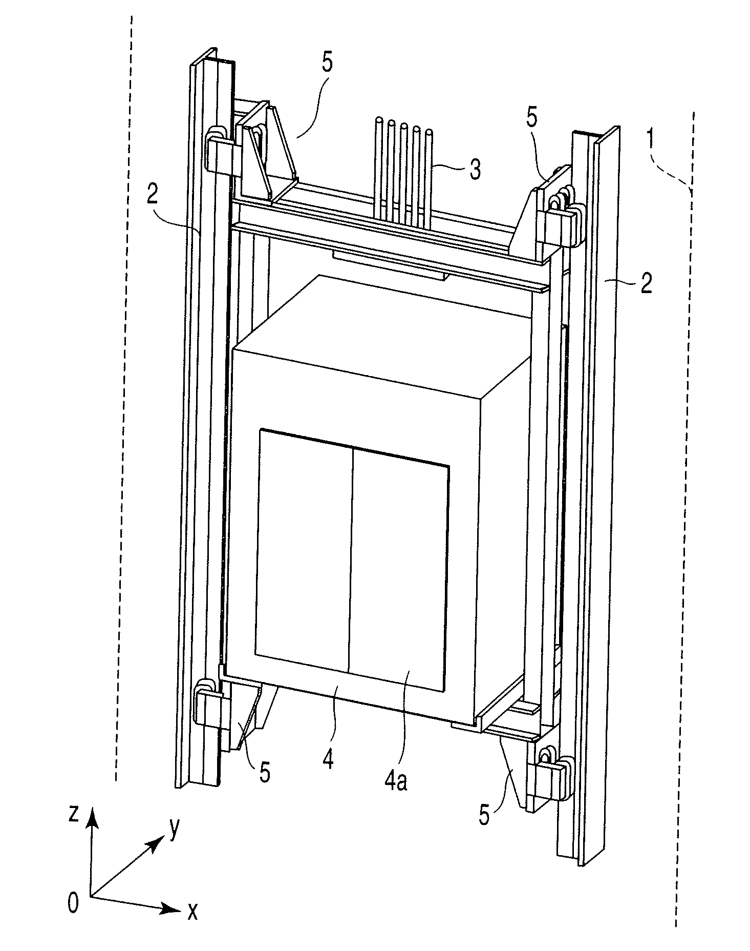
[0056]FIG. 1 is a perspective view in a case where a magnetic guide apparatus according to a first embodiment of the present invention is applied to a car of an elevator.
[0057]As is shown in FIG. 1, a pair of guide rails 2, which are formed of iron-made ferromagnetic bodies, are erectingly provided in an elevation path 1 of the elevator. A car 4 is suspended by ropes 3 which are wound around a hoister (not shown). With the rotation of the hoister, the car 4 is elevated along the guide rails 2. Reference numeral 4a denotes a car door. The car door 4a is opened / closed when the car 4 arrives at each floor.
[0058]It is assumed that when the car door 4a of the car 4 is viewed in the frontal direction, the right-and-left direction of the car door 4a is an x axis, the back-and-forth direction is a y axis, and the up-and-down direction is a z axis.
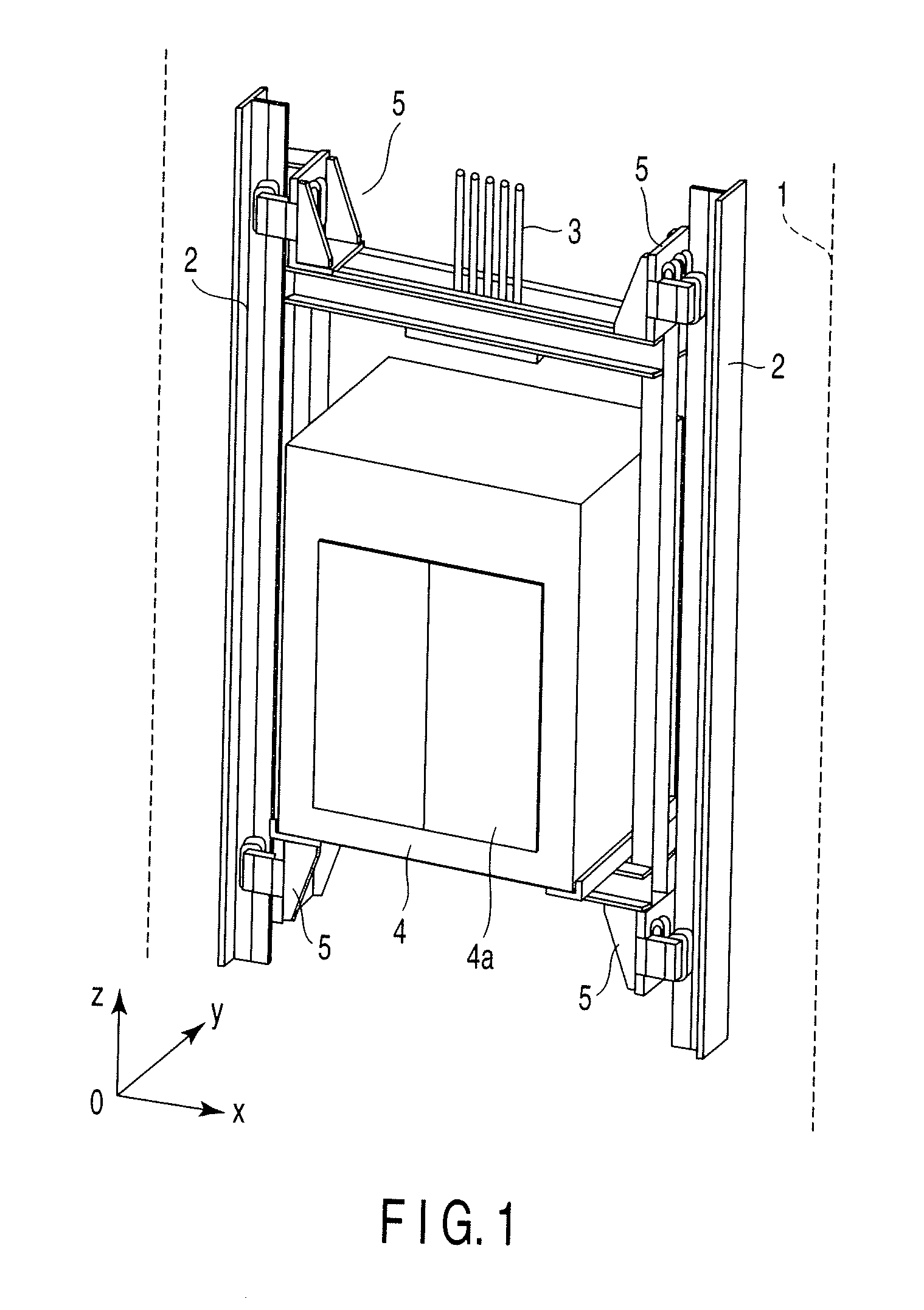
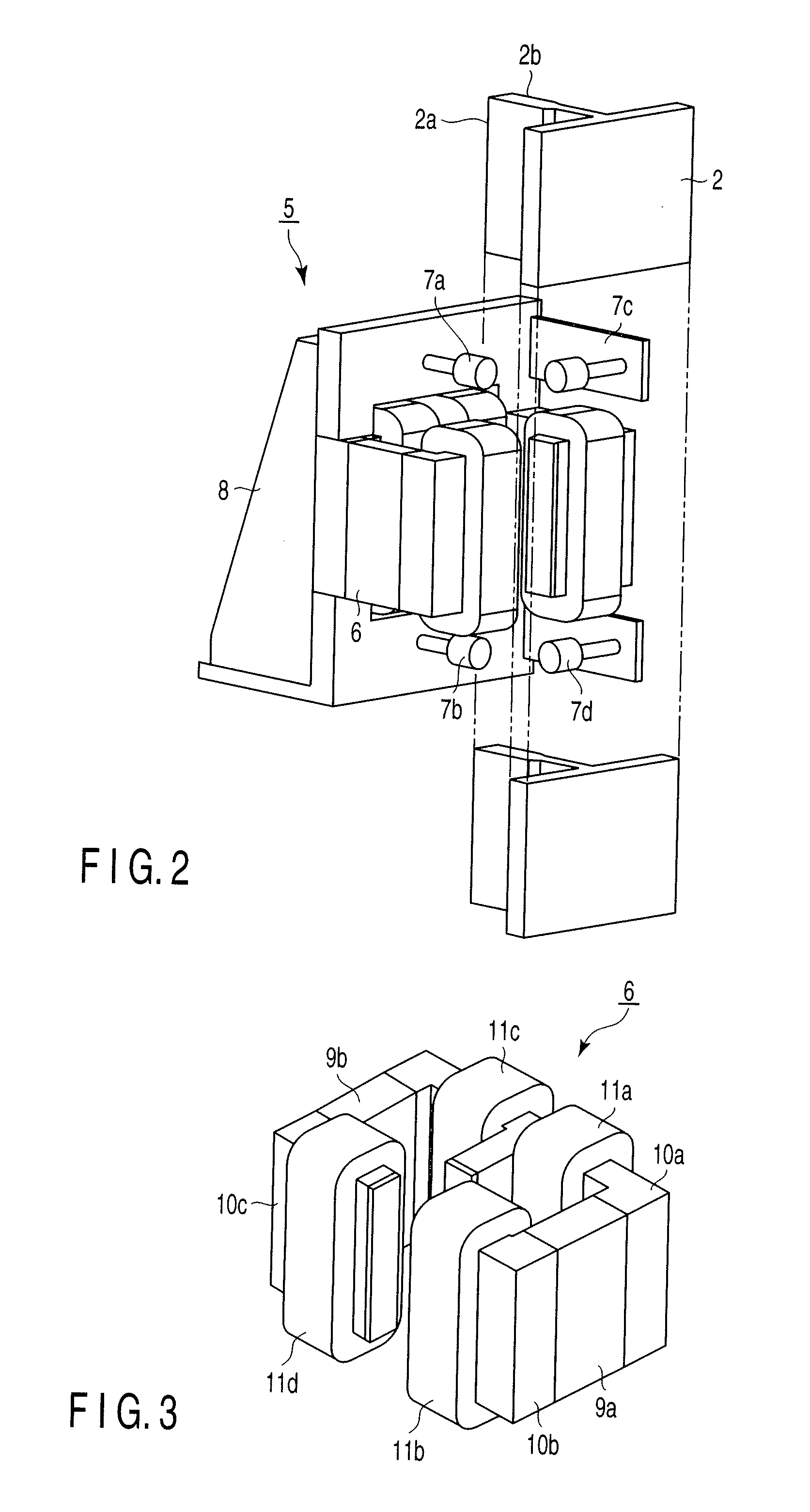
[0059]Magnetic guide apparatuses 5 are attached to coupling parts at four corners of the car 4, namely, upward, downward, leftward and rightward c...
second embodiment
[0105]Next, a second embodiment of the present invention is described.
[0106]In the second embodiment, the detection signal Ga of the gap sensor 7a and the detection signal Gb of the gap sensor 7b are subjected to second-order differentiation. The structure of the magnetic guide apparatus 5, etc., are the same as in the first embodiment.
[0107]FIG. 12 is a block diagram showing the structure of a signal correction arithmetic unit 31 according to the second embodiment of the present invention. The structural parts common to those of the first embodiment shown in FIG. 10 are denoted by like reference numerals, and a description thereof is omitted here.
[0108]In the second embodiment, the signal correction arithmetic unit 31 is provided with second-order differentiators 36a and 36b in place of the above-described differentiators 32a and 32b. Specifically, in the first embodiment, the detection signal Ga of the gap sensor 7a and the detection signal Gb of the gap sensor 7b are subjected to...
third embodiment
[0115]Next, a third embodiment of the present invention is described.
[0116]The third embodiment is configured such that the determination of variation amounts is executed by using a difference signal between a differential signal which is obtained a predetermined time before, and a differential signal obtained at the present time.
[0117]FIG. 14 is a block diagram showing the structure of a signal correction arithmetic unit 31 according to the third embodiment of the invention. The structural parts common to those of the first embodiment shown in FIG. 10 are denoted by like reference numerals, and a description thereof is omitted here.
[0118]In the third embodiment, the signal correction arithmetic unit 31 is provided with a memory 37a and a subtracter 102 on an output side of the differentiator 32a, and a memory 37b and a subtracter 103 on an output side of the differentiator 32b.
[0119]The memory 37a holds a differential signal that is obtained by the differentiator 32a. The subtract...
PUM
 Abstract
Description
Claims
Application Information