Magnetic guide apparatus

a technology of magnetic guide and roller guide, which is applied in the direction of elevators, transportation and packaging, etc., can solve the problems of vibration or noise, noise when the roller guide rotates, and the comfortablility of the elevator deteriorates

Inactive Publication Date: 2011-08-23
TOSHIBA ELEVATOR KK
View PDF15 Cites 9 Cited by
  • Summary
  • Abstract
  • Description
  • Claims
  • Application Information

AI Technical Summary

Benefits of technology

[0016]However, in the method of switching a plurality of sensor signals, as in KOKAI H11-71067, an input sensor signal for control becomes discontinuous, and as a result, the control of magnetic force becomes unstable. In addition, in the case where there is discontinuity between the plural sensor signals, the discontinuity is detected as a signal vibration at the time of switching, and as a result, the control becomes unstable.

Problems solved by technology

In this contact-type guide apparatus, however, vibration or noise occurs due to deformation of guide rails or joints of the guide rails.
In addition, noise occurs when the roller guides rotate.
Thus, there occurs a problem that the comfortablility of the elevator deteriorates.
At the parts of the joints, there are stepped portions due to the non-uniformity of the shapes of rails and the non-uniformity of the precision in disposition of rails, and the detection signal of the gap sensor is greatly disturbed instantaneously.
In addition, it the case of using a gap sensor utilizing physical properties of an object of detection, such as an eddy-current-type sensor, the detection signal at the part of the joint of the rails is disturbed more than a degree of actual variation.
As a result, the car is shaken, and such a problem arises that the comfortability in riding is affected.
However, in the method of switching a plurality of sensor signals, as in KOKAI H11-71067, an input sensor signal for control becomes discontinuous, and as a result, the control of magnetic force becomes unstable.
In addition, in the case where there is discontinuity between the plural sensor signals, the discontinuity is detected as a signal vibration at the time of switching, and as a result, the control becomes unstable.
However, when the car is actually greatly shaken by external disturbance, this movement cannot exactly be detected and the non-contact state cannot be maintained.
Besides, if the phase of the sensor signal is displaced, the stability of the control system deteriorates and thus a filter with a large-delay element cannot be used.

Method used


Image

  • Magnetic guide apparatus
  • Magnetic guide apparatus
  • Magnetic guide apparatus

Examples


first embodiment

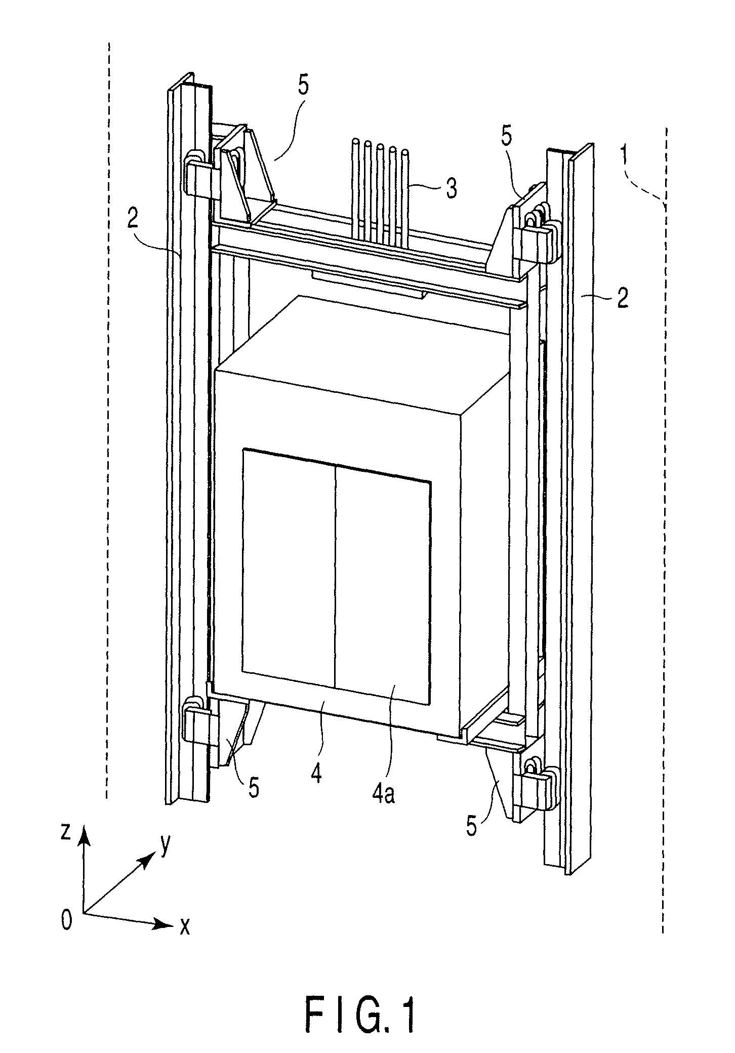
[0056]FIG. 1 is a perspective view in a case where a magnetic guide apparatus according to a first embodiment of the present invention is applied to a car of an elevator.

[0057]As is shown in FIG. 1, a pair of guide rails 2, which are formed of iron-made ferromagnetic bodies, are erectingly provided in an elevation path 1 of the elevator. A car 4 is suspended by ropes 3 which are wound around a hoister (not shown). With the rotation of the hoister, the car 4 is elevated along the guide rails 2. Reference numeral 4a denotes a car door. The car door 4a is opened / closed when the car 4 arrives at each floor.

[0058]It is assumed that when the car door 4a of the car 4 is viewed in the frontal direction, the right-and-left direction of the car door 4a is an x axis, the back-and-forth direction is a y axis, and the up-and-down direction is a z axis.

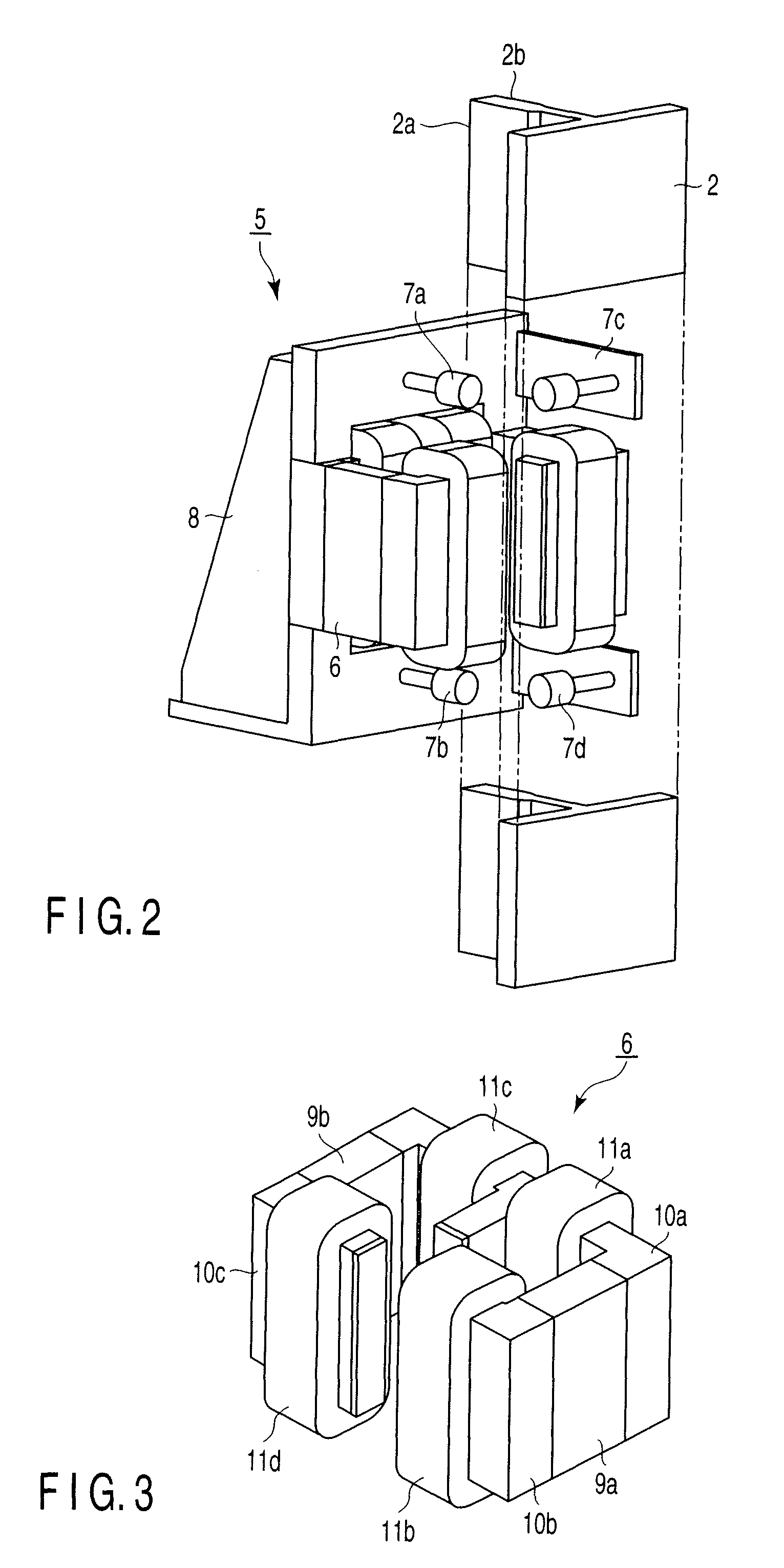
[0059]Magnetic guide apparatuses 5 are attached to coupling parts at four corners of the car 4, namely, upward, downward, leftward and rightward c...

second embodiment

[0106]Next, a second embodiment of the present invention is described.

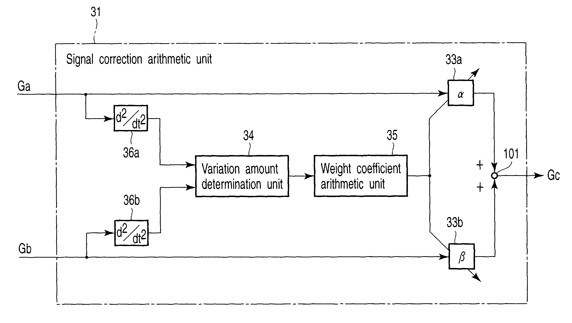
[0107]In the second embodiment, the detection signal Ga of the gap sensor 7a and the detection signal Gb of the gap sensor 7b are subjected to second-order differentiation. The structure of the magnetic guide apparatus 5, etc., are the same as in the first embodiment.

[0108]FIG. 12 is a block diagram showing the structure of a signal correction arithmetic unit 31 according to the second embodiment of the present invention. The structural parts common to those of the first embodiment shown in FIG. 10 are denoted by like reference numerals, and a description thereof is omitted here.

[0109]In the second embodiment, the signal correction arithmetic unit 31 is provided with second-order differentiators 36a and 36b in place of the above-described differentiators 32a and 32b. Specifically, in the first embodiment, the detection signal Ga of the gap sensor 7a and the detection signal Gb of the gap sensor 7b are subjected to...

third embodiment

[0116]Next, a third embodiment of the present invention is described.

[0117]The third embodiment is configured such that the determination of variation amounts is executed by using a difference signal between a differential signal which is obtained a predetermined time before, and a differential signal obtained at the present time.

[0118]FIG. 14 is a block diagram showing the structure of a signal correction arithmetic unit 31 according to the third embodiment of the invention. The structural parts common to those of the first embodiment shown in FIG. 10 are denoted by like reference numerals, and a description thereof is omitted here.

[0119]In the third embodiment, the signal correction arithmetic unit 31 is provided with a memory 37a and a subtracter 102 on an output side of the differentiator 32a, and a memory 37b and a subtracter 103 on an output side of the differentiator 32b.

[0120]The memory 37a holds a differential signal that is obtained by the differentiator 32a. The subtract...


PUM


Abstract

A magnetic guide apparatus includes at least two gap sensors which are disposed with a predetermined interval in a direction of movement of a moving body, and detect a gap between a magnet unit and a guide rail, a signal correction unit which determines variation amounts of detection signals which are output from the gap sensors, relatively varies weight coefficients for the respective detection signals on the basis of the variation amounts, and outputs, as a signal for magnetic control, a signal which is obtained by adding the detection signals which are multiplied by the weight coefficients, and a control unit which controls the magnetic force of the magnet unit on the basis of the signal for magnetic control, which is output from the signal correction unit.

Description

CROSS-REFERENCE TO RELATED APPLICATIONS[0001]This application is based upon and claims the benefit of priority from prior Japanese Patent Application No. 2007-235532, filed Sep. 11, 2007, the entire contents of which are incorporated herein by reference.BACKGROUND OF THE INVENTION[0002]1. Field of the Invention[0003]The present invention relates to a magnetic guide apparatus for non-contactly guiding the running of, for example, a car of an elevator along guide rails.[0004]2. Description of the Related Art[0005]In general, a car of an elevator is supported on a pair of guide rails which are vertically disposed in the elevation path, and the car is elevated by ropes which are wounded around a hoister. At this time, shaking of the car, which occurs due to imbalance of the load weight or movement of passengers, is suppressed by the guide rails.[0006]In usual cases, a contact-type guide apparatus is used as a guide apparatus for guiding the car in the direction of elevation. Specificall...

Claims


Application Information

Patent Timeline
Patent Type & Authority Patents(United States)
IPC IPC(8): B66B1/34
CPCB66B7/044
Inventor ITO, HIROAKI
Owner TOSHIBA ELEVATOR KK
Why Eureka
Try Eureka