Drive controller and drive control method for electric motor
a technology of drive controller and electric motor, which is applied in the direction of pulse technique, motor/generator/converter stopper, dynamo-electric converter control, etc., can solve the problem of possible instability of control operation
- Summary
- Abstract
- Description
- Claims
- Application Information
AI Technical Summary
Benefits of technology
Problems solved by technology
Method used
Image
Examples
embodiment 1
[0083](Control Mode Switching Process of Embodiment 1)
[0084]Next, the control mode switching process in accordance with Embodiment 1 of the present invention will be described.
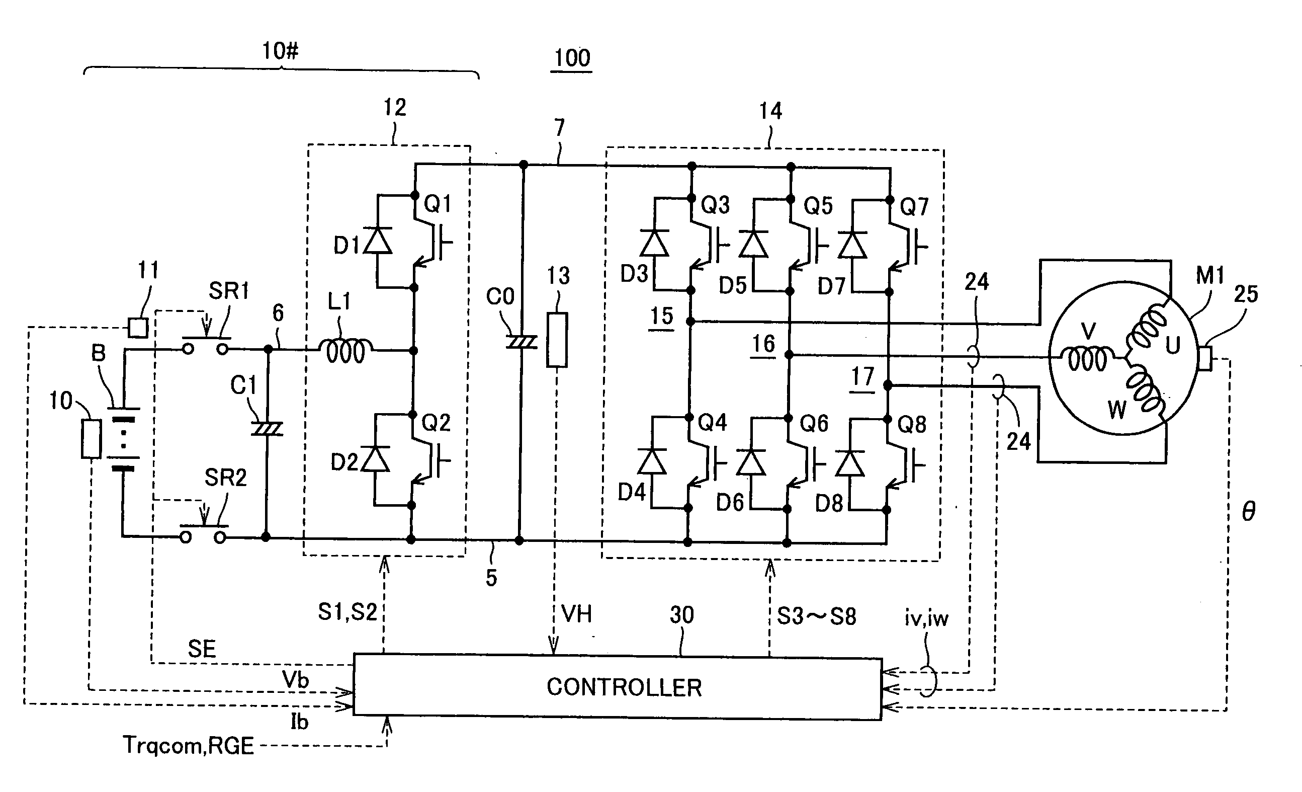
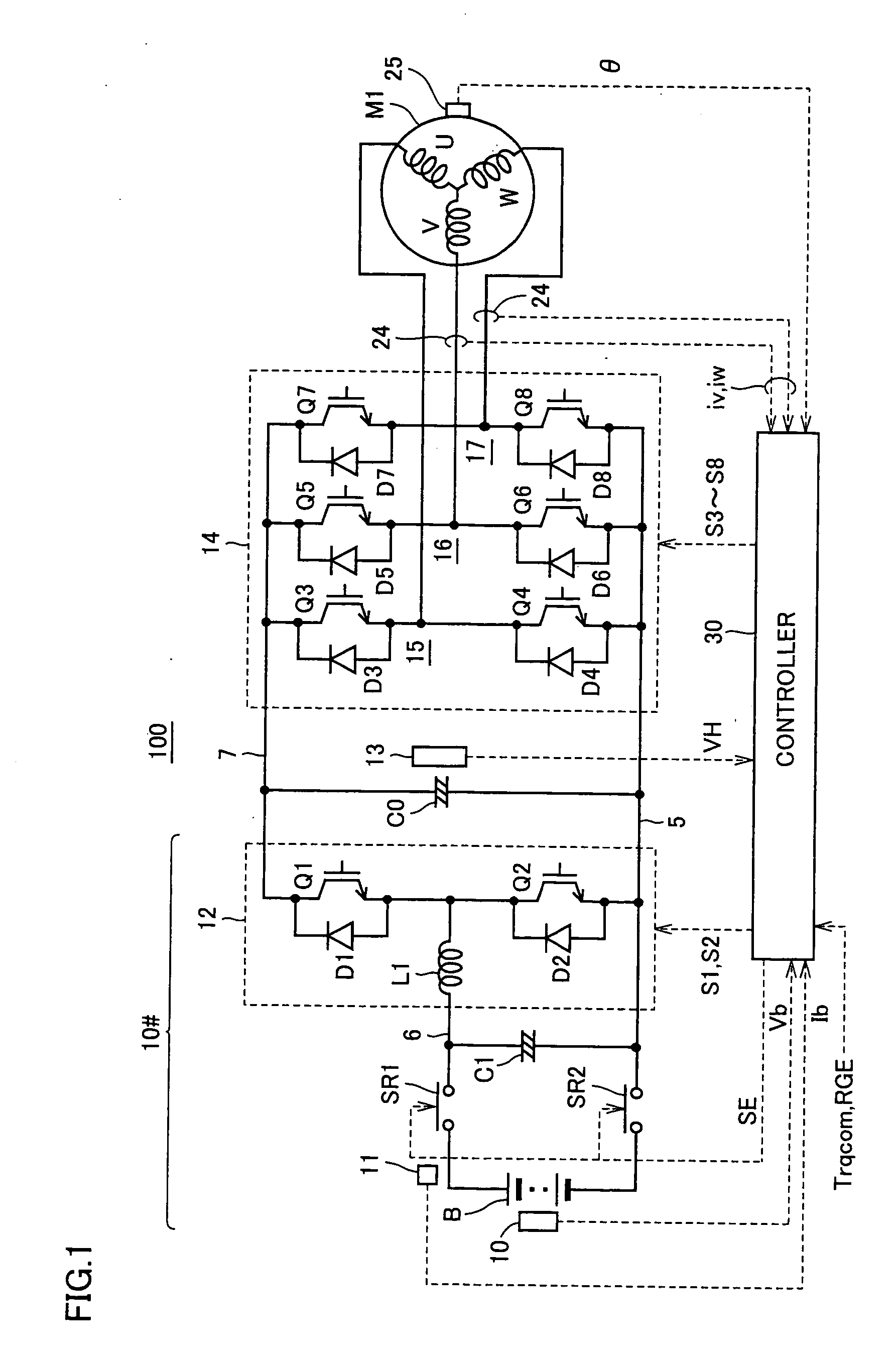
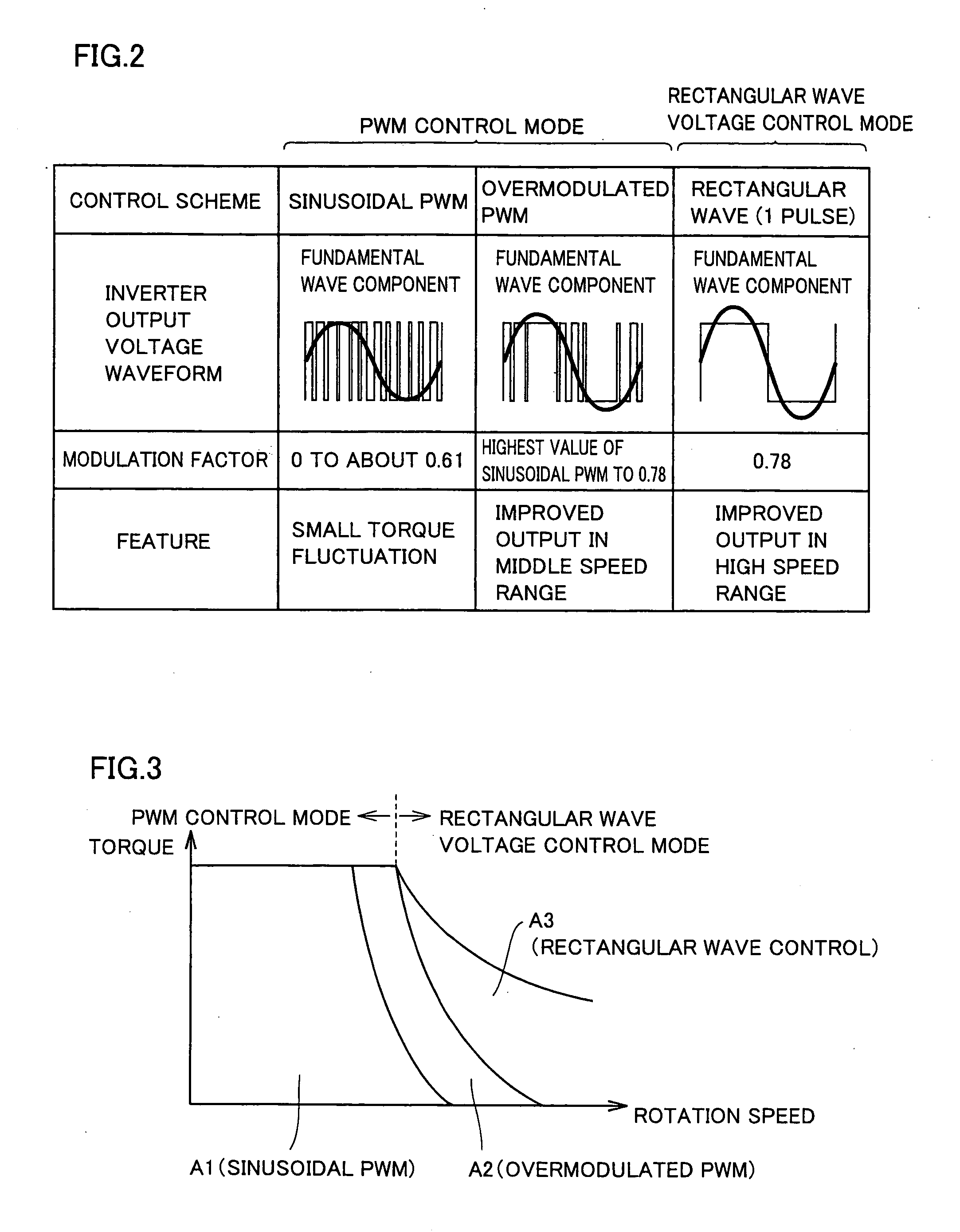
[0085]As shown in FIG. 4, mode switching determining unit 400 executes the mode switching determination based on the motor current MCRT detected by the current sensor, the input voltage VH of inverter 14 detected by voltage sensor 13, and the voltage amplitude |V| and voltage phase φv of the voltage command generated by current control unit 220. By way of example, when controller 30 executes the control process in accordance with the flowchart of FIG. 6, the mode switching determination by mode switching determining unit 400 is realized.
[0086]Referring to FIG. 6, first, controller 30 determines whether the present control mode is the PWM control mode or not, at step S100. If the present control mode is the PWM control mode (determination of YES at S100), controller 30 calculates, at step S110, a modulation fac...
embodiment 2
[0105](Control Mode Switching Process of Embodiment 2)
[0106]As described in Embodiment 1, in order to realize smooth transition of control mode, it is necessary that the result of control calculation for executing PWM control is already available by the time of control mode switching. In Embodiment 2, a control structure that allows immediate switching of control mode, without necessitating wait for one period of the main loop from the mode switching determination (from rectangular wave voltage control mode to the PWM control mode) by mode switching determining unit 400 will be described.
[0107]FIG. 10 is a flowchart representing the control calculation process in the rectangular wave control mode, by the drive controller for an AC electric motor in accordance with Embodiment 2.
[0108]Referring to FIG. 10, controller 30 determines, at step S200, whether the control mode is the rectangular wave voltage control-mode or not. If the rectangular wave voltage control mode is not selected (d...
PUM
 Abstract
Description
Claims
Application Information
 - R&D
- Intellectual Property
- Life Sciences
- Materials
- Tech Scout
- Unparalleled Data Quality
- Higher Quality Content
- 60% Fewer Hallucinations
Browse by: Latest US Patents, China's latest patents, Technical Efficacy Thesaurus, Application Domain, Technology Topic, Popular Technical Reports.
© 2025 PatSnap. All rights reserved.Legal|Privacy policy|Modern Slavery Act Transparency Statement|Sitemap|About US| Contact US: help@patsnap.com


