Conducting member and connector having conducting member

a technology of conducting member and connector, which is applied in the direction of connection contact member material, securing/insulating coupling contact member, coupling device connection, etc., can solve the problems of increasing the number of components, time and labor required for assembling the connector, and the difficulty of achieving a compact design of the connector, so as to reduce the number of components and compact the effect of size and compactness

Inactive Publication Date: 2009-04-09
YAZAKI CORP
View PDF30 Cites 21 Cited by
  • Summary
  • Abstract
  • Description
  • Claims
  • Application Information

AI Technical Summary

Benefits of technology

[0020]In the fifth aspect of the invention, the connector comprises the terminal connected to the end portion of the wire, the synthetic resin-made housing receiving the terminal therein, and the conducting member for connecting the terminal to the mating member of the conductive nature provided outside the housing, and the conducting member is a conducting member as defined in any one of the first to fourth aspects of the invention. Therefore, there can be provided the connector which has a reduced number of component parts, and is compact in size.
[0021]In the sixth aspect of the inv

Problems solved by technology

In the above conventional grounding-purpose connector, in order to connect the ground terminal to the grounding portion (that is, to the ground), several parts (that is, the shell, the earth metal member, the screw, etc.,) must be interposed therebetween, and therefore the number of the component parts increases, which has invited a problem that the time and labor required for assembling the connector increases.
Another problem is that it is diffic

Method used


Image

  • Conducting member and connector having conducting member
  • Conducting member and connector having conducting member
  • Conducting member and connector having conducting member

Examples


first embodiment

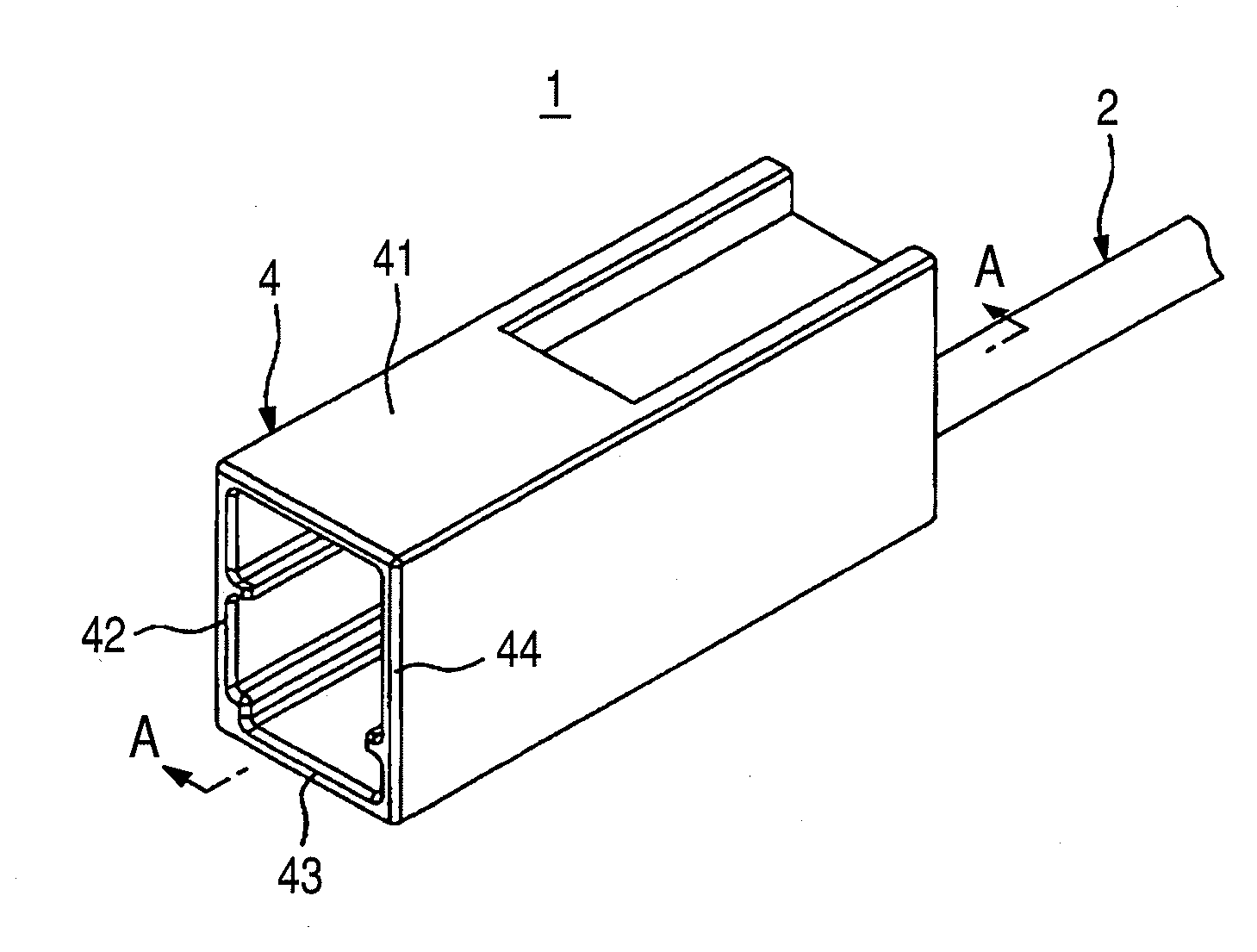
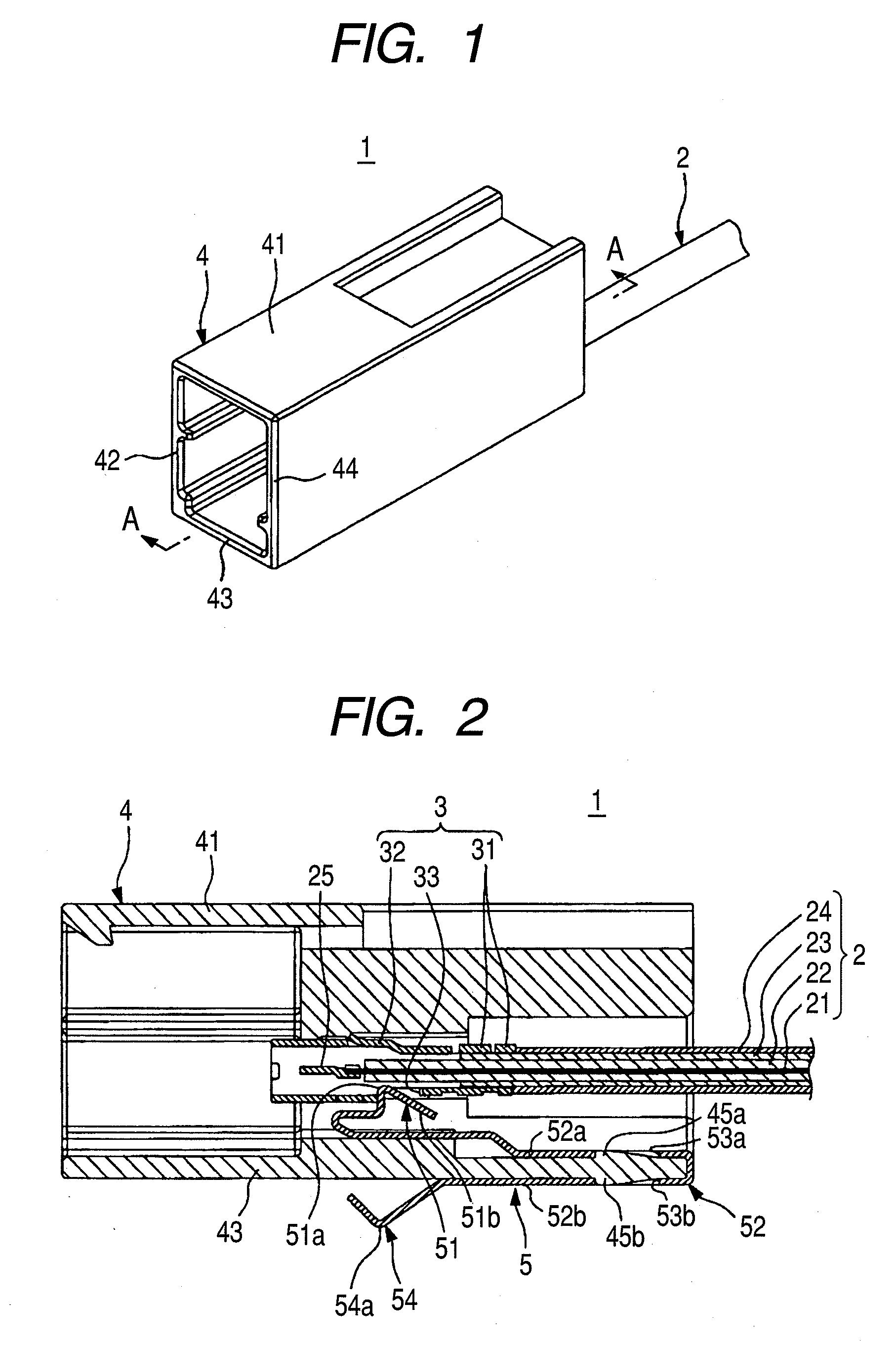
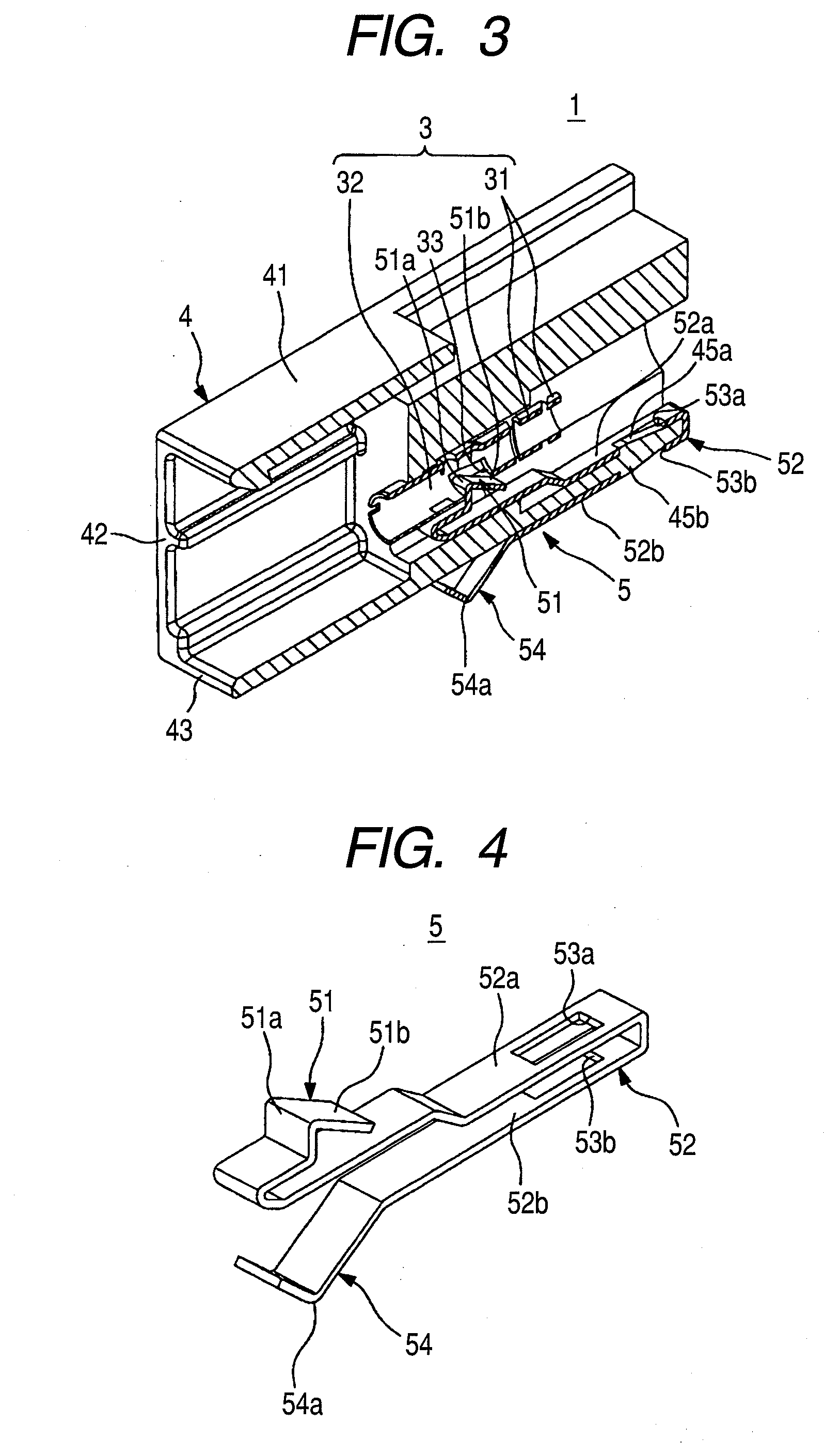
[0030]A first embodiment of a connector of the present invention will now be described with reference to FIGS. 1 to 4. FIG. 1 is a perspective view showing the connector of the first embodiment. FIG. 2 is a cross-sectional view taken along the line A-A of FIG. 1. FIG. 3 is a cross-sectional, perspective view taken along the line A-A of FIG. 1. In FIG. 3, the showing of a wire (cable) and an inner terminal connected to a core wire of the wire is omitted. FIG. 4 is a perspective view showing a conducting member of the connector of FIG. 2.

[0031]The connector 1 shown in FIGS. 1 to 3 is for use with a wire harness for installation on an automobile or the like, and this connector 1 comprises a ground terminal 3 (corresponding to a terminal in the claimed invention) connected to an end portion of the coaxial cable 2 (corresponding to a wire in the claimed invention), a synthetic resin-made housing 4 receiving the ground terminal 3 therein, and an earth plate 5 (corresponding to a conductin...

second embodiment

[0051]Next, a second embodiment of a connector of the invention will be described with reference to FIGS. 5 to 8. FIG. 5 is a cross-sectional, perspective view showing the connector of this second embodiment. In FIG. 5, the showing of a wire (cable) and an inner terminal connected to a core wire of the wire is omitted. FIG. 6 is a perspective view of a conducting member of the connector of FIG. 5. FIG. 7 is a perspective view showing a condition in which the conducting member and a terminal of the connector of FIG. 5 are connected together. FIG. 8 is a plan view showing the condition in which the conducting member and the terminal of the connector of FIG. 5 are connected together. In FIGS. 5 to 8, those portions identical in construction to those of the above first embodiment will be designated by identical reference numerals, respectively, and detailed description thereof will be omitted.

[0052]As shown in FIG. 5, the connector 101 of this embodiment comprises the ground terminal 3,...


PUM


Abstract

A connector includes a ground terminal connected to a braid shield of a coaxial cable at an end portion thereof, a housing receiving the ground terminal therein, and an earth plate for connecting the ground terminal to a mating member of a conductive nature provided outside the housing. The earth plate is formed by pressing a single metal sheet into a predetermined shape, and includes a housing retaining portion for being retainingly mounted on the housing, a terminal retaining/connecting portion for being engaged with the ground terminal to retain the ground terminal within the housing and also to be electrically connected to the ground terminal, and a grounding portion for electrical connection to the mating member.

Description

BACKGROUND OF THE INVENTION[0001]1. Field of the Invention[0002]This invention relates to a conducting member for connecting a terminal (received within a housing of a connector) to a mating member of a conductive nature provided outside the housing, and also relates to a connector having this conducting member.[0003]2. Related Art[0004]Wire harnesses are installed on an automobile so as to feed electric power and control signals to electronic equipments mounted on the automobile. Such a wire harness comprises a plurality of wires, and connectors connected to ends of these wires. The connector includes a conductive metal terminal connected to the wire, and an insulative housing receiving this metal terminal therein, and is connected to a connector of the electronic equipment.[0005]One known example of the above connectors is a grounding-purpose connector for connecting the wire to a suitable grounding portion (for example, a body of the vehicle serving as a mating member) so as to p...

Claims


Application Information

Patent Timeline
IPC IPC(8): H01R13/40
CPCH01R4/4809H01R4/646H01R9/0527H01R9/0512H01R9/034H01R13/65914
Inventor SHINKAWA, DAISUKEYAMAGUCHI, TORU
Owner YAZAKI CORP
Why Eureka
Try Eureka