Depth of Field Extension for Optical Tomography

a technology of optical tomography and depth of field, applied in the field of optical projection tomography, can solve the problem of limited speed of the focal plane moving through the specimen

Active Publication Date: 2009-04-23
VISIONGATE
View PDF69 Cites 93 Cited by
  • Summary
  • Abstract
  • Description
  • Claims
  • Application Information

AI Technical Summary

Problems solved by technology

By using a PZT actuator to move the objective lens, a focal plane moving through the specimen has its speed limited by inertia inherent in moving the objective lens mass rapidly along the optical axis through the specimen.

Method used


Image

  • Depth of Field Extension for Optical Tomography
  • Depth of Field Extension for Optical Tomography
  • Depth of Field Extension for Optical Tomography

Examples


example 1

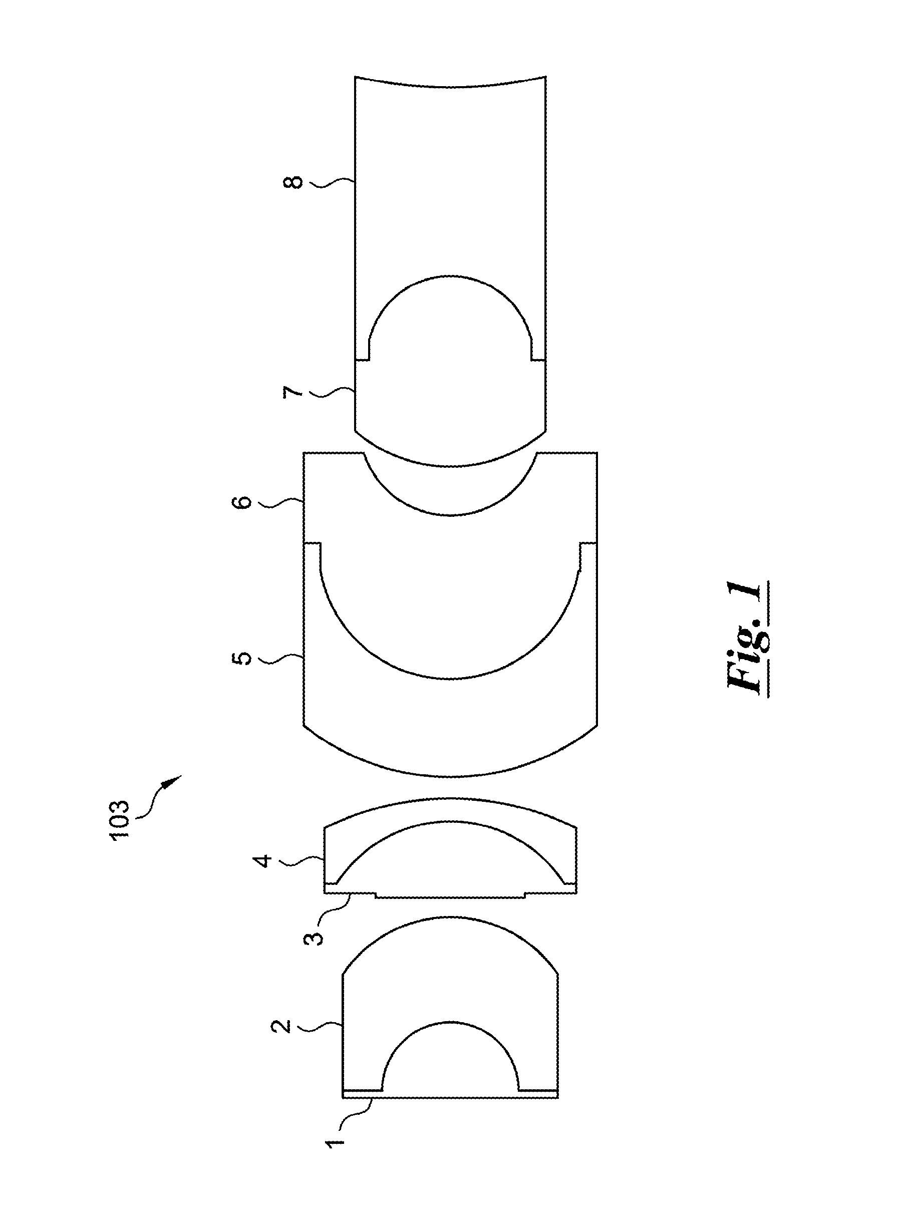
[0052]One example of a hyperchromatic objective lens 103, suitable for use in a hyperchromatic system, is depicted in FIG. 1. This compound lens comprises eight optical elements 1-8 of which optical elements 1 and are cemented together to form a first doublet, and optical elements 3 and 4 are cemented together to form a second doublet, 5 and 6 are cemented together to form a third doublet, and 7 and 8 are cemented together to form a fourth doublet. The first surface of 1 is flat or slightly convex, so as to avoid trapping air in a cavity when this surface comes in contact with an immersion liquid such as oil or water. An example prescription for the objective 103 follows.

MaterialFront RadiusBack RadiusCenter(Schottof Curvatureof CurvatureThicknessElementdesignation)(mm)(mm)(mm)1SF57200−3.173.54LAK143.17−5.925.08Air——13KZFSN4104.5−6.553.644SF66.55−13.771Air——15SF6410.736.274.756LASF40−6.274.477.88Air——2.247SK27.23−3.959.058F23.9519.378.83

The location of the aperture stop may be chose...


PUM


Abstract

An optical projection tomography system is illuminated with a light source. An object-containing tube, a portion of which is located within the region illuminated by the light source, contains an object of interest that has a feature of interest. A detector is located to receive emerging radiation from the object of interest. A lens, including optical field extension elements, is located in the optical path between the object region and the detector, such that light rays from multiple object planes in the object-containing tube simultaneously focus on the detector. The object-containing tube moves relatively to the detector and the lens operate to provide multiple views of the object region for producing an image of the feature of interest at each view.

Description

TECHNICAL FIELD[0001]The present invention relates to optical tomographic imaging systems in general, and, more particularly, to optical projection tomography, in which a small object, such as a biological cell, is positioned in a capillary tube for imaging by a microscope.BACKGROUND[0002]Advances in imaging biological cells using optical tomography have been developed by Nelson as disclosed, for example, in U.S. Pat. No. 6,522,775, issued Feb. 18, 2003, and entitled “Apparatus and method for imaging small objects in a flow stream using optical tomography,” the full disclosure of which is incorporated by reference. Further developments in the field are taught in Fauver et al., U.S. patent application Ser. No. 10 / 716,744, filed Nov. 18, 2003 and published as US Publication No. US-2004-0076319-A1 on Apr. 22, 2004, entitled “Method and apparatus of shadowgram formation for optical tomography,” (Fauver '744) and Fauver et al., U.S. patent application Ser. No. 11 / 532,648, filed Sep. 18, ...

Claims


Application Information

Patent Timeline
Patent Type & Authority Applications(United States)
IPC IPC(8): G06K9/78
CPCA61B5/0073G01N21/4795G01N15/1468
Inventor RAHN, J. RICHARDHAYENGA, JON W.
Owner VISIONGATE
Why Eureka
Try Eureka