Test tube structure

A test tube and integrated technology, applied in the field of test tube structure, can solve the problems of no auxiliary measures, cumbersome and slow registration process, etc., and achieve the effect of increasing the speed of positioning the rotation center

Pending Publication Date: 2018-04-17
FOSHAN UNIVERSITY
View PDF0 Cites 0 Cited by
  • Summary
  • Abstract
  • Description
  • Claims
  • Application Information

AI Technical Summary

Problems solved by technology

[0003] At present, there is a problem that the deviation between the projection center and the rotation center needs to be corrected in the process of OPT reconstruction tomography. The above problems are solved in the prior art by directly correcting the deviation of the rotation center of the projected sinogram and registering the reconstruction map. The main methods are iterative method, based on The rotation center calculation method of the center of mass motion trajectory and the image registration algorithm, but the above methods all need to load the test tube with the sample on a motor device used to drive the test tube to rotate in the process of processing, so as to obtain the sample at different angles. Projecting images, and then converting the projected images into corresponding sinograms, and since all of the conventional test tubes are used without any auxiliary measures, it leads to the correction of a series of sinogram rotation center deviations and the reconstruction image using the above method The registration process is relatively cumbersome and slow

Method used


Image

  • Test tube structure
  • Test tube structure

Examples


Embodiment Construction

[0015] In the following, the concept, specific structure, and technical effects of the present invention will be clearly and completely described in conjunction with the embodiments and the drawings to fully understand the purpose, features and effects of the present invention. Obviously, the described embodiments are only a part of the embodiments of the present invention, rather than all the embodiments. Based on the embodiments of the present invention, other embodiments obtained by those skilled in the art without creative work belong to The scope of protection of the present invention. In addition, all the connection / connection relationships mentioned in the text do not only refer to the direct connection of the components, but refer to the fact that a better connection structure can be formed by adding or reducing connection accessories according to specific implementation conditions. The various technical features in the invention can be combined interactively on the pre...


PUM


Abstract

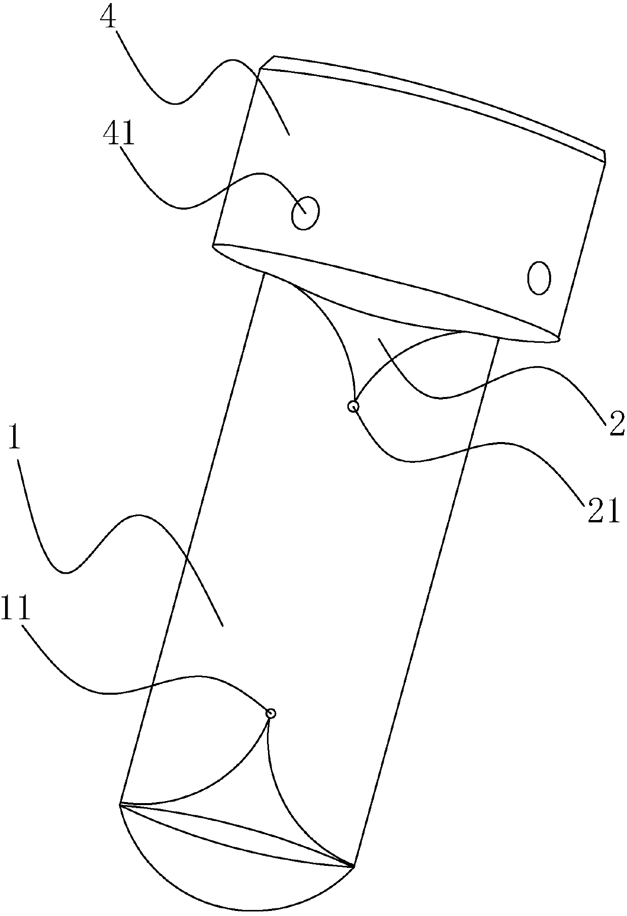
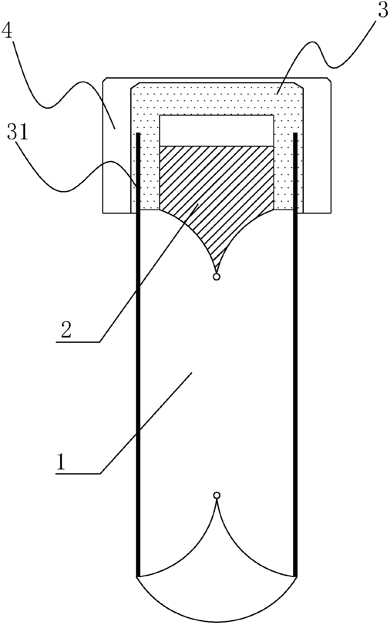
The invention discloses a test tube structure, which comprises a glass tube body and a glass plug. The glass tube body is provided with an opening. The glass plug is arranged at the opening of the glass tube body to form a sealed cavity with the glass tube body. A marker, the first marker is close to the bottom of the glass tube, the second marker is provided on the side of the glass stopper, the second marker is inserted into the glass tube, the first marker and the second marker are both off the center of the glass tube axis. When processing the projected image, the present invention calculates the camera centerline and the deviation of the rotation center by means of the projected sinogram of the first marker and the fault where the second marker is located, so that the speed of positioning the rotation center is significantly improved, and at the same time after positioning the rotation center The sinogram reconstruction of the obtained slice artifacts is less, and the slice contour and shape are more in line with the real situation. The invention is used for loading samples during optical projection tomography.

Description

Technical field [0001] The invention relates to the technical field of test tube structures. Background technique [0002] Optical projection tomography (OPT) technology is a technology to reconstruct object slice images on the basis of projection images. This technology uses multi-angle projection to reconstruct a series of projected sinograms with the obtained projection data. The slice tomogram is obtained through the reconstruction algorithm. [0003] The current OPT reconstruction process has the problem of correcting the deviation between the projection center and the rotation center. In the prior art, the above problems are solved by directly correcting the projection sinogram rotation center deviation and registering the reconstructed image. The main methods include iterative method and based on The centroid motion trajectory is calculated based on the center of rotation and the image registration algorithm. However, the above methods need to load the test tube with the sa...

Claims


Application Information

Patent Timeline
Patent Type & Authority Applications(China)
IPC IPC(8): B01L3/14
CPCB01L3/5082B01L3/50825
Inventor 熊红莲林秋萍王茗祎黎思娜曾亚光韩定安王磊吕秋皓
Owner FOSHAN UNIVERSITY
Why Eureka
Try Eureka